![[ANSYS, Inc. Logo]](fluentlogo.gif)


|
|
|
In previous versions of ANSYS FLUENT, user-defined scalar (UDS) equations could only be solved in fluid zones. This restriction is now removed. As a result, the Fuel Cell and Electrolysis module allows you to model current collectors as solid, as well as fluid zones. One advantage of using solids as the current collector is that the convergence of the species equations are not hindered by the potentially skewed mesh inside the current collectors.
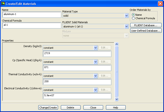
If fluid zones are used to model solid current collectors, ANSYS FLUENT automatically set velocities to zero and cuts off species transport into these zones. If solid zones are used, however, you need to activate the solution of the electric potential (UDS-0) in these solid zones (see the separate ANSYS FLUENT User's Guide for details). The value of the Electric Conductivity for the solid material needs to be assigned in the Create/Edit Materials dialog.
|
|
Note that the
UDS Diffusivity should be set to
user-defined (cond::fuelcells). Do not use the
defined-per-uds option.
|
For more information on the user-defined scalar diffusivity, see the separate ANSYS FLUENT User's Guide.
Note that the Fuel Cell and Electrolysis Model allows you to model current collectors either as porous media zones (if you want to allow for mass and momentum transport within the collectors) or as solid zones.
Previous:
2.6.7 Reporting on the