![[ANSYS, Inc. Logo]](fluentlogo.gif)


|
|
|
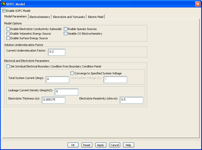
You can specify the general settings for the SOFC With Unresolved Electrolyte Model using the Model Parameters tab in the SOFC Model dialog.
From this tab, you can set the various parameters for the SOFC With Unresolved Electrolyte Model such as total system current, electrolyte thickness, electrolyte resistivity, etc.
The Enable Electrolyte Conductivity Submodel option allows the ionic conductivity (or resistivity) of the electrolyte to change as a function of temperature. At the moment, there is one correlation that provides ionic conductivity (or resistivity) of the electrolyte as function of temperature.
|
|
Note that this is valid only for temperatures ranging from 1073 K to 1373 K.
|
By turning off the Enable Surface Energy Source option, ANSYS FLUENT excludes the heat addition due to electrochemistry and all the reversible processes. This option should be turned on at all times.
The Enable Volumetric Energy Source option includes the ohmic heating throughout the electrically conducting zones. You should keep this option turned off (to avoid slowing the convergence rates) until a certain rate of convergence for the potential field has been achieved, at which point, you should turn the option on manually. Note that this option is important so that the solution can account for the efffects of the internal Ohmic heating.
The Disable CO Electrochemistry is enabled if there is carbon monoxide (CO) in the fuel line and if you do not want to include the CO in the electrochemistry.
Since the calculations are very sensitive to large current fluctuations early in the solution process, it is recommended to use 0.3 or 0.4 for the Current Underrelaxation Factor for a more effective solution.
The leakage current is the total amount of current due to the leakage of oxidizer to the fuel side (through the electrolyte) and the electric current across the electrolyte due to any short circuit. You can specify a value for the leakage current under Leakage Current Density.
If the leakage current density is temperature-dependent, you can specify your own temperature-dependent implementation of the leakage current density by performing the following steps:
For more information, see Section 4.8.1.
The Converge to Specified System Voltage is used when the you want to specify a system voltage instead of system current as an input.
The Set Individual Electrical Boundary Condition from Boundary Conditions Panel option, when enabled, allows you to directly specify the current density or voltage for each individual current-collecting boundary using the ANSYS FLUENT Boundary Conditions task page, This allows you to apply multiple current types or multiple voltage types (either constant or variable) to your boundary conditions.
Previous:
4.3 Solid Oxide Fuel