[ANSYS, Inc. Logo] return to home search
next up previous contents

Step 8: Mesh Interfaces

figure Mesh Interfaces

  In this step, you will create a non-conformal mesh interface between the hexahedral and tetrahedral meshes.

figure Mesh Interfaces figure Create/Edit...

figure

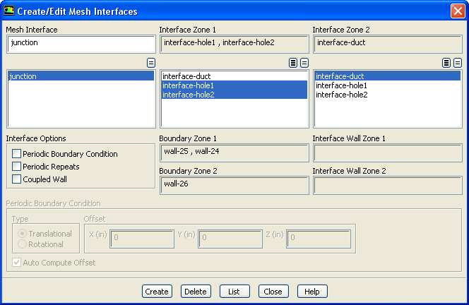
1.   Select interface-hole1 and interface-hole2 in the Interface Zone 1 selection list.

figure   

When one interface zone is smaller than the other, choose the smaller zone as Interface Zone 1.

2.   Select interface-duct from the Interface Zone 2 selection list.

3.   Enter junction for Mesh Interface.

4.   Click Create.

  In the process of creating the mesh interface, ANSYS FLUENT will create three new wall boundary zones: wall-24, wall-25, and wall-26.

  • wall-24 and wall-25 are the non-overlapping regions of the interface-hole1 and interface-zone2 zones that result from the intersection of the interface-hole1, interface-hole2, and interface-duct boundary zones. They are listed under Boundary Zone 1 in the Create/Edit Mesh Interfaces dialog box. These wall boundaries are empty, since interface-hole1 and interface-hole2 are completely contained within the interface-duct boundary.

  • wall-26 is the non-overlapping region of the interface-duct zone that results from the intersection of the three interface zones, and is listed under Boundary Zone 2 in the Create/Edit Mesh Interfaces dialog box.

You will not be able to display these walls.

figure   

You need to set boundary conditions for wall-26 (since it is not empty). In this case, the default settings are used.

5.   Close the Create/Edit Mesh Interfaces dialog box.


next up previous contents Previous: Step 7: Boundary Conditions
Up: Using a Non-Conformal Mesh
Next: Step 9: Solution
Release 12.0 © ANSYS, Inc. 2009-02-09