You can use the
Advanced tab of the
Fuel Cell and Electrolysis Models dialog to specify the contact resistivity for any material interface in the geometry, set parameters for coolant channels, and define fuel stack units for managing stacks of fuel cells.
Setting Contact Resistivities for the Fuel Cell and Electrolysis Model
Figure 2.6.13: The
Advanced Tab of the
Fuel Cell and Electrolysis Models Dialog for Contact Resistivities
1.
Select the
Advanced tab of the
Fuel Cell and Electrolysis Models dialog.
2.
Select
Contact Resistivity under
Advanced Setup.
3.
Select any number of corresponding interfaces from the
Available Zone(s) list. These zones are face zones over which a jump in electrical potential is caused by imperfect conduction.
4.
Specify a value for the
Resistivity for each specified zone.
5.
To simplify the input, you can choose to use the resistivity value of the first selected zone for all others as well by turning on the
Use First Value for All option.
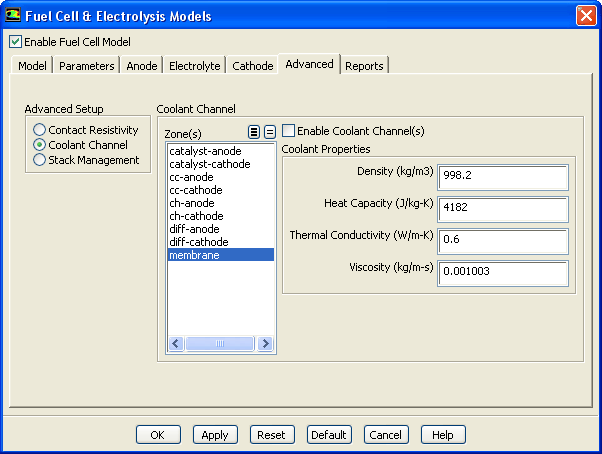
Setting Coolant Channel Properties for the Fuel Cell and Electrolysis Model
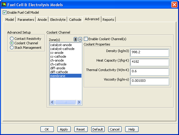
Figure 2.6.14: The
Advanced Tab of the
Fuel Cell and Electrolysis Models Dialog for the Coolant Channel
1.
Select the
Advanced tab of the
Fuel Cell and Electrolysis Models dialog.
2.
Select
Coolant Channel under
Advanced Setup.
3.
Select any number of corresponding zones from the
Zone(s) list.
4.
Specify a value for the
Density.
5.
Specify a value for the
Heat Capacity.
6.
Specify a value for the
Thermal Conductivity.
7.
Specify a value for the
Viscosity.
8.
To enable the coolant channel, turn on the
Enable Coolant Channel(s) option. Amongst other settings, this will change the mixture to include the coolant species, which is otherwise absent.
Managing Stacks for the Fuel Cell and Electrolysis Model
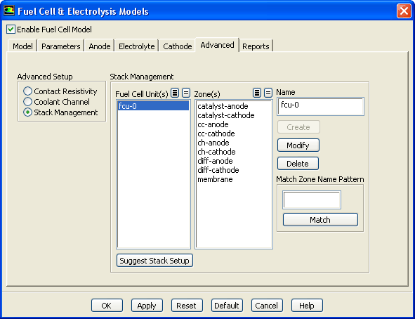
Figure 2.6.15: The
Advanced Tab of the
Fuel Cell and Electrolysis Models Dialog for Stack Management
The
ANSYS FLUENT Fuel Cell and Electrolysis Model allows you to model fuel cell stacks as well as individual fuel cells. In the
Advanced tab of the
Fuel Cell and Electrolysis Models dialog, you can define
fuel cell units for each fuel cell in a stack. A fuel cell unit consists of all zones of a single fuel cell in the stack.
If you are only modeling a single fuel cell, then you do not need to set anything for
Stack Management in the
Advanced tab of the
Fuel Cell and Electrolysis Models dialog.
1.
Select the
Advanced tab of the
Fuel Cell and Electrolysis Models dialog.
2.
Select
Stack Management under
Advanced Setup.
3.
Since a fuel cell unit consists of all zones of a single fuel cell in the stack, select the corresponding zones from the
Zone(s) list.
4.
Create a new fuel cell unit by clicking the
Create button. The new fuel cell is listed under
Fuel Cell Unit(s) with a default name.
5.
Edit a pre-existing fuel cell unit by selecting it in the
Fuel Cell Unit(s) list. The zones in this fuel cell unit are automatically selected in the
Zone(s) list. You can then modify the zones that comprise the fuel cell unit and/or change its name in the
Name field and click
Modify to save the new settings.
6.
Remove a pre-existing fuel cell unit by selecting it in the
Fuel Cell Unit(s) list and clicking the
Delete button.
7.
If your model contains many zone names, you can use the
Match Zone Name Pattern field to specify a pattern to look for in the names of zones. Type the pattern in the text field and click
Match to select (or deselect) the zones in the
Zones list with names that match the specified pattern. You can match additional characters using
* and
?. For example, if you specify
wall*, all surfaces whose names begin with
wall (e.g.,
wall-1,
wall-top) will be selected automatically. If they are all selected already, they will be deselected. If you specify
wall?, all surfaces whose names consist of
wall followed by a single character will be selected (or deselected, if they are all selected already).
For example, in a stack there are many fuel cells, say 10 - 100, each having at least 9 zones (current collector, gas channel, diffusion layer, and catalyst layer for both anode and cathode and a membrane). Additionally, there may be coolant channels, and it may be that for mesh construction reasons each of these physical zones is made up of more than one mesh zone. Even for small stacks, you can easily end up having hundreds of cell zones in an
ANSYS FLUENT mesh. Therefore, you may want to consider numbering the fuel cells in a stack and to use the assigned fuel cell number in the names of the mesh zones. When you set up your stacked fuel cell case, you would use the
Match Zone Name Pattern field to pick all the zones belonging to a single fuel cell in the stack, rather than scrolling through the potentially very long list and selecting them manually.
8.
You can have
ANSYS FLUENT attempt to automatically determine the zones that constitute a single fuel cell in a stack using the
Suggest Stack Setup button. Manually performing this task is often time-consuming and error-prone. Using the
Suggest Stack Setup button can save you from having to manually enter this information yourself for potentially hundreds of zones.
When using the
Suggest Stack Setup button,
ANSYS FLUENT needs to correctly identify electrically conducting parts and their connectivity (anode, electrolyte, cathode, coolant channels, and external contacts) using zone information generally required by the fuel cell model anyway.
ANSYS FLUENT requires zone information to have been specified in
all of the following tabs in the
Fuel Cell and Electrolysis Models dialog:
In the
Anode tab, specify zone information for the current collector, the porous electrode, and the TPB catalyst layer.
In the
Electrolyte tab, specify zone information for the electrolyte/membrane.
In the
Cathode tab, specify zone information for the current collector, the porous electrode, and the TPB catalyst layer.
In the
Advanced tab, specify zone information for the coolant channel.
In the
Reports tab, specify the external contact interface(s).
In the
Advanced tab, click the
Suggest Stack Setup button.
If your fuel cell model inputs are incorrect (or incomplete),
ANSYS FLUENT cannot completely be sure that the resulting setup is correct. Also, even if your inputs are correct, an unconventional fuel cell design may cause
ANSYS FLUENT to suggest an inaccurate stack setup. So, it is your responsibility to verify the stack setup prior to clicking either the
OK or the
Apply buttons.
![[ANSYS, Inc. Logo]](fluentlogo.gif)