[ANSYS, Inc. Logo] return to home search
next up previous contents


Step 3: Models

figure Models

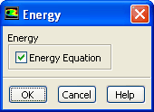
1.   Enable heat transfer by enabling the energy equation.

figure Models figure figure Energy figure Edit...

figure

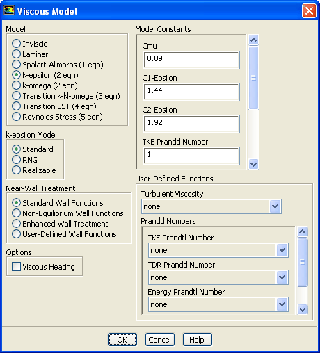
2.   Select the standard $k$- $\epsilon$ turbulence model.

figure Models figure figure Viscous figure Edit...

figure

(a)   Select k-epsilon in the Model list.

  The Viscous Model dialog box will expand to provide further options for the k-epsilon model.

(b)   Retain the default settings for the k-epsilon model.

(c)   Click OK to close the Viscous Model dialog box.

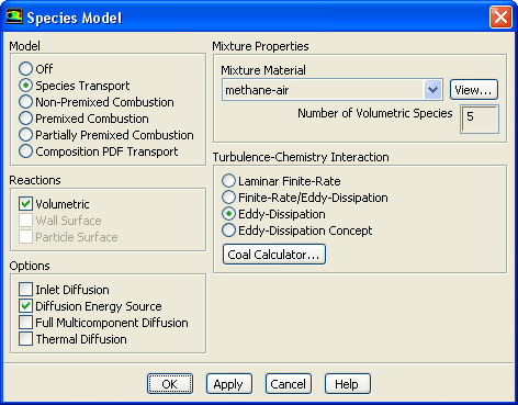
3.   Enable chemical species transport and reaction.

figure Models figure figure Species figure Edit...

figure

(a)   Select Species Transport in the Model list.

  The Species Model dialog box will expand to provide further options for the Species Transport model.

(b)   Enable Volumetric in the Reactions group box.

(c)   Select methane-air from the Mixture Material drop-down list.

  Scroll down the list to find methane-air.

Note:   The Mixture Material list contains the set of chemical mixtures that exist in the ANSYS FLUENT database. You can select one of the predefined mixtures to access a complete description of the reacting system. The chemical species in the system and their physical and thermodynamic properties are defined by your selection of the mixture material. You can alter the mixture material selection or modify the mixture material properties using the Create/Edit Materials dialog box (see Step 4: Materials).

(d)   Select Eddy-Dissipation in the Turbulence-Chemistry Interaction group box.

  The eddy-dissipation model computes the rate of reaction under the assumption that chemical kinetics are fast compared to the rate at which reactants are mixed by turbulent fluctuations (eddies).

(e)   Click OK to close the Species Model dialog box.

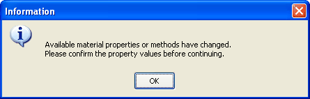
  An Information dialog box will open, reminding you to confirm the property values before continuing. Click OK to continue.

figure

   ANSYS FLUENT will display a warning about the symmetry zone in the console, prior to listing the properties that are required for the models you have enabled (you may have to scroll up to see this warning).

Warning: It appears that symmetry zone 5 should actually be an axis
         (it has faces with zero area projections).
         Unless you change the zone type from symmetry to axis,
         you may not be able to continue the solution without
         encountering floating point errors.


  In the axisymmetric model, the boundary conditions should be such that the centerline is an axis type instead of a symmetry type. You will change the symmetry zone to an axis boundary in Step 5: Boundary Conditions.


next up previous contents Previous: Step 2: General Settings
Up: Modeling Species Transport and
Next: Step 4: Materials
Release 12.0 © ANSYS, Inc. 2009-02-09