![[ANSYS, Inc. Logo]](fluentlogo.gif)


|
|
|
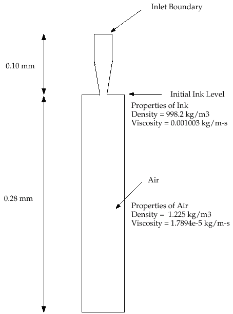
The problem considers the transient tracking of a liquid-gas interface in the geometry shown in Figure 18.1. The axial symmetry of the problem allows a 2D geometry to be used. The computation mesh consists of 24,600 cells. The domain consists of two regions: an ink chamber and an air chamber. The dimensions are summarized in Table 18.1.
| Ink Chamber, Cylindrical Region: Radius (mm) | 0.015 |
| Ink Chamber, Cylindrical Region: Length (mm) | 0.050 |
| Ink Chamber, Tapered Region: Final Radius (mm) | 0.009 |
| Ink Chamber, Tapered Region: Length (mm) | 0.050 |
| Air Chamber: Radius (mm) | 0.030 |
| Air Chamber: Length (mm) | 0.280 |
The following is the chronology of events modeled in this simulation:
The calculation is run for 30 microseconds overall, i.e., three times longer than the duration of the initial impulse.
Because the dimensions are small, the double-precision version of ANSYS FLUENT will be used. Air will be designated as the primary phase, and ink (which will be modeled with the properties of liquid water) will be designated as the secondary phase. Patching will be required to fill the ink chamber with the secondary phase. Gravity will not be included in the simulation. To capture the capillary effect of the ejected ink, the surface tension and prescription of the wetting angle will be specified. The surface inside the nozzle will be modeled as neutrally wettable, while the surface surrounding the nozzle orifice will be non-wettable.
Previous:
Prerequisites