- 1.
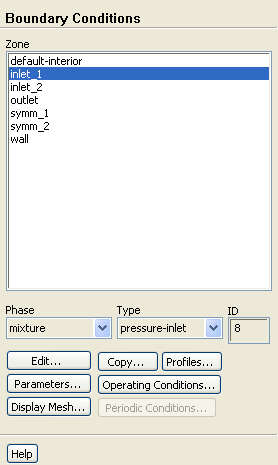
Set the boundary conditions at
inlet_1 for the mixture.
 Boundary Conditions

 inlet_1
 Edit...
- (a)
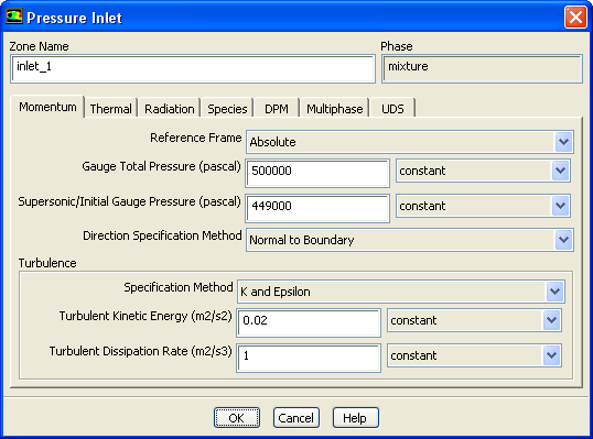
Enter
500000
 for
Gauge Total Pressure.
for
Gauge Total Pressure.
- (b)
Enter
449000
 for
Supersonic/Initial Gauge Pressure.
for
Supersonic/Initial Gauge Pressure.
-
If you choose to initialize the solution based on the pressure-inlet conditions, the
Supersonic/Initial Gauge Pressure will be used in conjunction with the specified stagnation pressure (the
Gauge Total Pressure) to compute initial values according to the isentropic relations (for compressible flow) or Bernoulli's equation (for incompressible flow). Otherwise, in an incompressible flow calculation the
Supersonic/Initial Gauge Pressure input will be ignored by
ANSYS FLUENT. In this problem the velocity will be initialized based on the difference between these two values.
- (c)
Retain the default selection of
Normal to Boundary from the
Direction Specification Method drop-down list.
- (d)
Retain the default selection of
K and Epsilon from the
Specification Method drop-down list in the
Turbulence group box.
- (e)
Enter
0.02
 for
Turbulent Kinetic Energy.
for
Turbulent Kinetic Energy.
- (f)
Retain the value of
1
 for
Turbulent Dissipation Rate.
for
Turbulent Dissipation Rate.
- (g)
Click
OK to close the
Pressure Inlet dialog box.
- 2.
Set the boundary conditions at
inlet-1 for the secondary phase.
 Boundary Conditions

 inlet_1
- (a)
Select
vapor from the
Phase drop-down list.
- (b)
Click
Edit... to open the
Pressure Inlet dialog box.
- i.
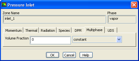
Click the
Multiphase tab and retain the default value of
0 for
Volume Fraction.
- ii.
Click
OK to close the
Pressure Inlet dialog box.
- 3.
Copy the boundary conditions defined for the first pressure inlet zone (
inlet_1) to the second pressure inlet zone (
inlet_2).
 Boundary Conditions

 inlet_1
- (a)
Select
mixture from the
Phase drop-down list.
- (b)
Click
Copy... to open the
Copy Conditions dialog box.
- i.
Select
inlet_1 from the
From Boundary Zone selection list.
- ii.
Select
inlet_2 from the
To Boundary Zones selection list.
- iii.
Click
Copy.
-
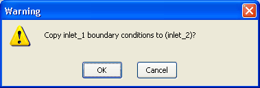
A
Warning dialog box will open, asking if you want to copy
inlet_1 boundary conditions to
inlet_2. Click
OK.
- iv.
Close the
Copy Conditions dialog box.
- 4.
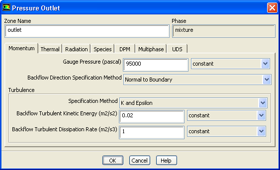
Set the boundary conditions at
outlet for the mixture.
 Boundary Conditions

 outlet
 Edit...
- (a)
Enter
95000
 for
Gauge Pressure.
for
Gauge Pressure.
- (b)
Retain the default selection of
K and Epsilon from the
Specification Method drop-down list in the
Turbulence group box.
- (c)
Enter
0.02
 for
Backflow Turbulent Kinetic Energy.
for
Backflow Turbulent Kinetic Energy.
- (d)
Retain the value of
1
 for
Backflow Turbulent Dissipation Rate.
for
Backflow Turbulent Dissipation Rate.
- (e)
Click
OK to close the
Pressure Outlet dialog box.
- 5.
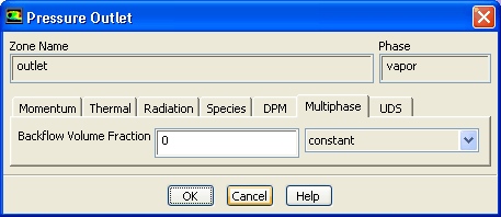
Set the boundary conditions at
outlet for the secondary phase.
 Boundary Conditions

 outlet
- (a)
Select
vapor from the
Phase drop-down list.
- (b)
Click
Edit... to open the
Pressure Outlet dialog box.
- i.
Click the
Multiphase tab and retain the default value of
0 for
Volume Fraction.
- ii.
Click
OK to close the
Pressure Outlet dialog box.
![[ANSYS, Inc. Logo]](fluentlogo.gif)


 Boundary Conditions