- 1.
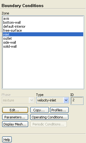
Set the boundary conditions for the inlet (
inlet).
 Boundary Conditions

 inlet
inlet
 Edit...
- (a)
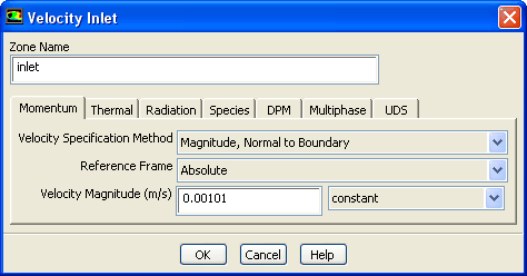
Enter
0.00101
 for
Velocity Magnitude.
for
Velocity Magnitude.
- (b)
Click the
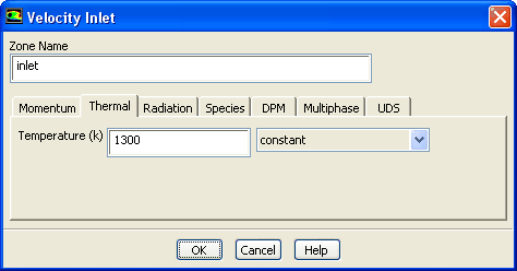
Thermal tab and enter
1300
 for
Temperature.
for
Temperature.
- (c)
Click
OK to close the
Velocity Inlet dialog box.
- 2.
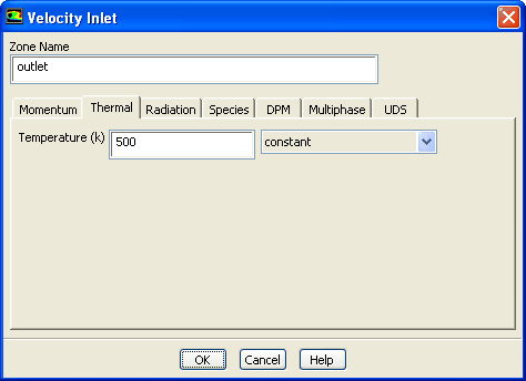
Set the boundary conditions for the outlet (
outlet).
 Boundary Conditions

 outlet
 Edit...
-
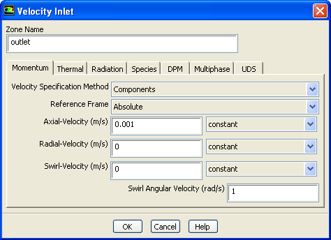
Here, the solid is pulled out with a specified velocity, so a velocity inlet boundary condition is used with a positive axial velocity component.
- (a)
Select
Components from the
Velocity Specification Method drop-down list.
-
The
Velocity Inlet dialog box will change to show related inputs.
- (b)
Enter
0.001
 for
Axial-Velocity.
for
Axial-Velocity.
- (c)
Enter
1
 for
Swirl Angular Velocity.
for
Swirl Angular Velocity.
- (d)
Click the
Thermal tab and enter
500
 for
Temperature.
for
Temperature.
- (e)
Click
OK to close the
Velocity Inlet dialog box.
- 3.
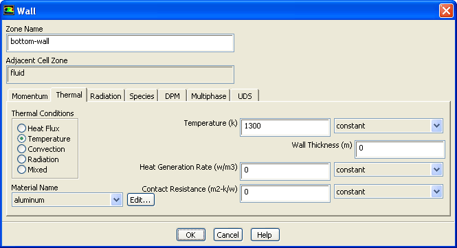
Set the boundary conditions for the bottom wall (
bottom-wall).
 Boundary Conditions

 bottom-wall
 Edit...
- (a)
Click the
Thermal tab.
- i.
Select
Temperature from the
Thermal Conditions group box.
- ii.
Enter
1300
 for
Temperature.
for
Temperature.
- (b)
Click
OK to close the
Wall dialog box.
- 4.
Set the boundary conditions for the free surface (
free-surface).
 Boundary Conditions

 free-surface
 Edit...
-
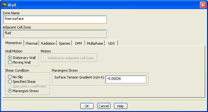
The specified shear and Marangoni stress boundary conditions are useful in modeling situations in which the shear stress (rather than the motion of the fluid) is known. A free surface condition is an example of such a situation. In this case, the convection is driven by the Marangoni stress and the shear stress is dependent on the surface tension, which is a function of temperature.
- (a)
Select
Marangoni Stress from the
Shear Condition group box.
-
The
Marangoni Stress condition allows you to specify the gradient of the surface tension with respect to temperature at a wall boundary.
- (b)
Enter
-0.00036
 for
Surface Tension Gradient.
for
Surface Tension Gradient.
- (c)
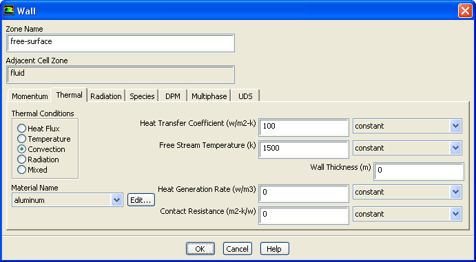
Click the
Thermal tab to specify the thermal conditions.
- i.
Select
Convection from the
Thermal Conditions group box.
- ii.
Enter
100
 for
Heat Transfer Coefficient.
for
Heat Transfer Coefficient.
- iii.
Enter
1500
 for
Free Stream Temperature.
for
Free Stream Temperature.
- (d)
Click
OK to close the
Wall dialog box.
- 5.
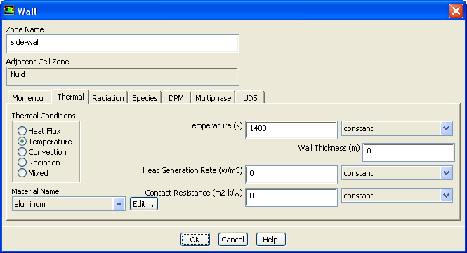
Set the boundary conditions for the side wall (
side-wall).
 Boundary Conditions

 side-wall
 Edit...
- (a)
Click the
Thermal tab.
- i.
Select
Temperature from the
Thermal Conditions group box.
- ii.
Enter
1400
 for the
Temperature.
for the
Temperature.
- (b)
Click
OK to close the
Wall dialog box.
- 6.
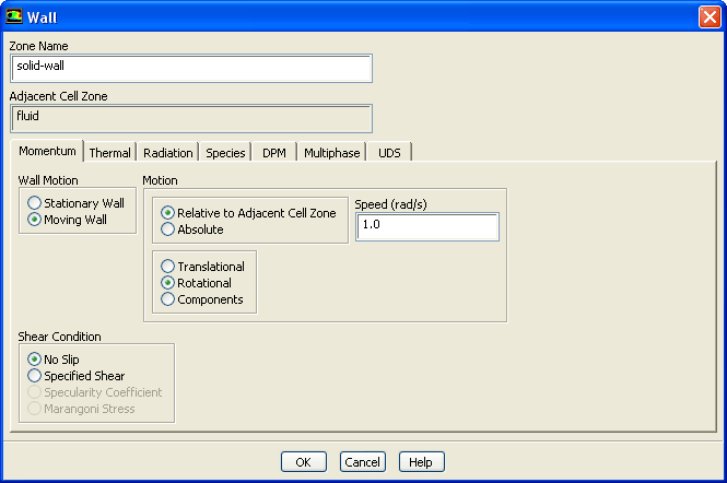
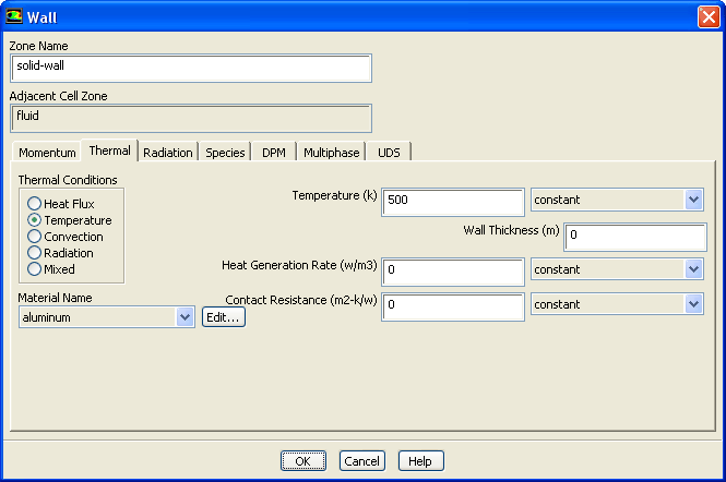
Set the boundary conditions for the solid wall (
solid-wall).
 Boundary Conditions

 solid-wall
 Edit...
- (a)
Select
Moving Wall from the
Wall Motion group box.
-
The
Wall dialog box will expand to show additional parameters.
- (b)
Select
Rotational in the lower box of the
Motion group box.
-
The
Wall dialog box will change to show the rotational speed.
- (c)
Enter
1.0
 for
Speed.
for
Speed.
- (d)
Click the
Thermal tab to specify the thermal conditions.
- i.
Select
Temperature from the
Thermal Conditions selection list.
- ii.
Enter
500
 for
Temperature.
for
Temperature.
- (e)
Click
OK to close the
Wall dialog box.
![[ANSYS, Inc. Logo]](fluentlogo.gif)


 Boundary Conditions