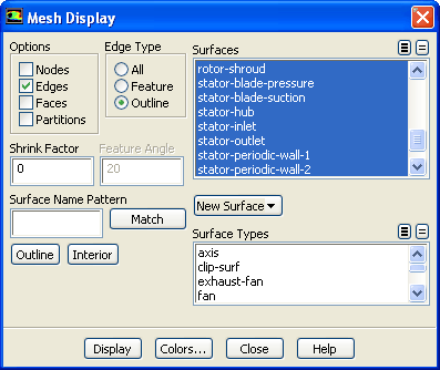
(a)
Retain the default
Edges option in the
Options group box.
(b)
Select
Outline in the
Edge Type list.
(c)
Deselect all the surfaces from the
Surfaces selection list and click the
Outline button.
(d)
Click
Display.
(e)
Rotate the view by clicking the
Rotate View icon (
) in the toolbar, press the left mouse button and drag the mouse. To zoom in or out, press the
Zoom In/Out button
and press the left mouse button and move the mouse up and down. To obtain an isometric display, select the
Isometric view icon
in the toolbar.
(f)
Close the
Mesh Display dialog box.
Extra:
You can use the right mouse button to check which zone number corresponds to each boundary. If you click the right mouse button on one of the boundaries displayed in the graphics window, its zone number, name, type, and other variables will be printed in the console. This feature is especially useful when you have several zones of the same type and you want to distinguish between them quickly.
![[ANSYS, Inc. Logo]](fluentlogo.gif)


 General
 General
 Display...
 ) in the toolbar, press the left mouse button and drag the mouse. To zoom in or out, press the
Zoom In/Out button
) in the toolbar, press the left mouse button and drag the mouse. To zoom in or out, press the
Zoom In/Out button
 and press the left mouse button and move the mouse up and down. To obtain an isometric display, select the
Isometric view icon
and press the left mouse button and move the mouse up and down. To obtain an isometric display, select the
Isometric view icon
 in the toolbar.