-
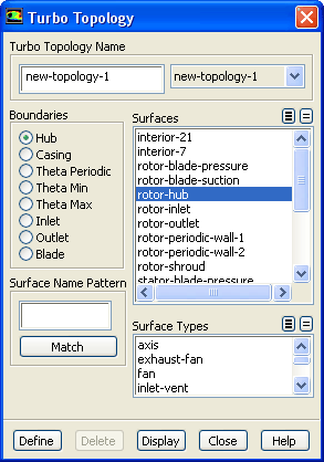
You will define the topologies of the flow domain in order to establish a turbomachinery-specific coordinate system. This coordinate system is used in subsequent postprocessing functions. Specifically, you will select the boundary zones that comprise the hub, shroud, inlet, outlet, and periodics. The boundaries may consist of more than one zone. The topologies that you define will be saved to the case file when you save the current model. Thus, if you read the saved case back into
ANSYS FLUENT, you do not need to set up the topology again.
For more information on defining turbomachinery topologies, see
this section in the separate
User's Guide.
Define
 Turbo Topology...
- 1.
Specify the surfaces representing the hub.
- (a)
Retain the default selection of
Hub in the
Boundaries group box.
- (b)
Select the surface that represent the hub (
rotor-hub) in the
Surfaces selection list.
- 2.
Specify the surfaces representing the casing.
- (a)
Select
Casing in the
Boundaries group box.
- (b)
Select
rotor-shroud in the
Surfaces selection list.
- 3.
Specify the surfaces representing theta periodic.
-
Theta periodic are all rotationally periodic boundary conditions surfaces (periodic boundary condition type) which border the turbo topology on the lateral (pitchwise) boundaries.
- (a)
Select
Theta Periodic in the
Boundaries group box.
- (b)
Select
rotor-periodic-wall-1 and
rotor-periodic-wall-2 in the
Surfaces selection list.
- 4.
Specify the surfaces representing theta min.
- (a)
Select
Theta Min in the
Boundaries group box.
- (b)
Select
rotor-blade-suction
in the
Surfaces selection list.
-
Theta Min and
Theta Max are all walls which may border the turbo topology on the lateral (pitchwise) boundaries. The "min'' and "max'' are determined by the right hand rule about the axis of rotation. Specifically, using the right hand rule, the min surfaces would have the minimum pitchwise coordinate and the max surfaces would have the maximum pitchwise coordinate.
- 5.
Specify the surfaces representing theta max.
- (a)
Select
Theta Max in the
Boundaries group box.
- (b)
Select
rotor-blade-pressure in the
Surfaces selection list.
- 6.
Specify the surface representing the inlet.
- (a)
Select
Inlet in the
Boundaries group box.
- (b)
Select
rotor-inlet in the
Surfaces selection list.
- 7.
Specify the surface representing the outlet.
- (a)
Select
Outlet in the
Boundaries group box.
- (b)
Select
rotor-outlet in the
Surfaces selection list.
- 8.
Retain the default name of
new-topology-1 for the
Turbo Topology Name.
- 9.
Click
Define to set all the turbomachinery boundaries.
-
Create a second topology to represent the stator.
- 10.
Specify the surfaces representing the hub.
- (a)
Select
Hub in the
Boundaries group box.
- (b)
Select the surface that represent the hub (
stator-hub) in the
Surfaces selection list.
-
Hint:
Scroll down the
Surfaces list to locate the surfaces representing the hub.
- 11.
Specify the surfaces representing the casing.
- (a)
Select
Casing in the
Boundaries group box.
- (b)
Select
stator-shroud in the
Surfaces selection list.
- 12.
Specify the surfaces representing theta periodic.
- (a)
Select
Theta Periodic in the
Boundaries group box.
- (b)
Select
stator-periodic-wall-1 and
stator-periodic-wall-2 in the
Surfaces selection list.
- 13.
Specify the surfaces representing theta min.
- (a)
Select
Theta Min in the
Boundaries group box.
- (b)
Select
stator-blade-suction
in the
Surfaces selection list.
- 14.
Specify the surfaces representing theta max.
- (a)
Select
Theta Max in the
Boundaries group box.
- (b)
Select
stator-blade-pressure in the
Surfaces selection list.
- 15.
Specify the surface representing the inlet.
- (a)
Select
Inlet in the
Boundaries group box.
- (b)
Select
stator-inlet in the
Surfaces selection list.
- 16.
Specify the surface representing the outlet.
- (a)
Select
Outlet in the
Boundaries group box.
- (b)
Select
stator-outlet in the
Surfaces selection list.
- 17.
Retain the default name of
new-topology-2 for the
Turbo Topology Name.
- 18.
Click
Define to set all the turbomachinery boundaries.
- 19.
Close the
Turbo Topology dialog box.
-
ANSYS FLUENT will inform you that the turbomachinery postprocessing functions have been enabled, and the
Turbo menu will appear in
ANSYS FLUENT menu bar at the top of the console. You can define any number of turbo topologies in the
Turbo Topology dialog box. This is especially useful when you have a model comprising multiple blade rows and you need to define more than one blade row simultaneously. Each topology can be assigned a specific name and accessed using the drop-down list in the
Turbo Topology dialog box.
For more information on defining turbomachinery topologies, see
this section in the separate
User's Guide.
-
Note:
You can display the selected surfaces by clicking the
Display button in the
Turbo Topology dialog box. This is useful as a graphical check to ensure that all relevant surfaces have been selected.


 Previous:
Step 2: General Settings
Previous:
Step 2: General Settings
Up:
Turbo Postprocessing
Next:
Step 4: Isosurface Creation
Release 12.0 © ANSYS, Inc. 2009-02-09 ![[ANSYS, Inc. Logo]](fluentlogo.gif)

