To display results in a 3D model, you will need surfaces on which the data can be displayed.
ANSYS FLUENT creates surfaces for all boundary zones automatically. In a general application, you may want to define additional surfaces for viewing results. The turbo postprocessing capabilities of
ANSYS FLUENT allow you to define more complex surfaces, specific to the application and the particular topology that you defined. In this step, you will create surfaces of iso-meridional (marching along the streamwise direction) and spanwise (distance between the hub and the shroud) coordinates in the compressor.
1.
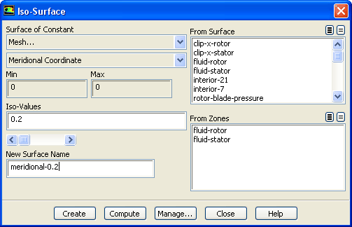
Create surfaces of constant meridional coordinate.
SurfaceIso-Surface...
(a)
Select
Mesh... and
Meridional Coordinate from the
Surface of Constant drop-down lists.
(b)
Enter
0.2 in the
Iso-Values text field.
(c)
Enter
meridional-0.2 for
New Surface Name.
(d)
Click
Create.
Note:
The isovalues you enter for these turbo-specific surfaces are expressed as a percentage of the entire domain (i.e., you just defined a surface of meridional coordinate equal to 20% of the path along the duct).
(e)
Similarly, define surfaces of meridional coordinates equal to 0.4, 0.6, and 0.8.
2.
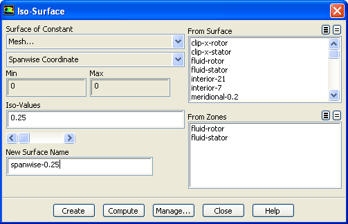
Create surfaces of constant spanwise coordinate.
(a)
Select
Mesh... and
Spanwise Coordinate from the
Surface of Constant drop-down lists.
(b)
Enter
0.25 in the
Iso-Values text field.
(c)
Enter
spanwise-0.25 for
New Surface Name.
(d)
Click
Create.
(e)
Similarly, define surfaces of spanwise coordinates equal to 0.5 and 0.75.
![[ANSYS, Inc. Logo]](fluentlogo.gif)


 Iso-Surface...