[ANSYS, Inc. Logo] return to home search
next up previous contents

Step 1B: Network of Computers

You can start the 3D parallel version of ANSYS FLUENT on a network of Windows, Linux, or UNIX machines using 2 processes and check the network connectivity by performing the following steps:

1.   In FLUENT Launcher, restore the default settings by clicking the Default button.

2.   Specify 3D for Dimension.

3.   Select Parallel (Local Machine) under Processing Options.

4.   Set the Number of Processes to 2.

5.   Click the Show More $>>$ button and select the Parallel Settings tab.
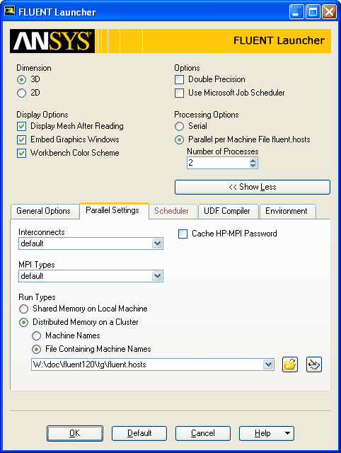
  • Retain the selection of default in the Interconnects and MPI Types drop-down lists.

  • Select Distributed Memory on a Cluster.

  • Make sure that File Containing Machine Names is selected to specify the file.

  • Type the name and location of the hosts text file in the text box below File Containing Machine Names, or browse and select it using the Browsing Machine File dialog box.

      Alternatively, you can select Machine Names and type the names of the machines in the text box.

6.   Click OK.

figure

You can also start parallel ANSYS FLUENT by typing the following at the command prompt:

fluent 3d -t2 -cnf=fluent.hosts

where -cnf indicates the location of the hosts text file. The hosts file is a text file that contains a list of the computers on which you want to run the parallel job. If the hosts file is not located in the directory where you are typing the startup command, you will need to supply the full pathname to the file.

For example, the fluent.hosts file may look like the following:

my_computer
another_computer

For additional information about hosts files and parallel command line options, see this chapter in the separate User's Guide.

7.   Check the network connectivity information.

  Although ANSYS FLUENT displays a message confirming the connection to each new compute node and summarizing the host and node processes defined, you may find it useful to review the same information at some time during your session, especially if more compute nodes are spawned to several different machines.

Parallel $\rightarrow$ Network $\rightarrow$ Show Connectivity...

figure

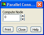
(a)   Set Compute Node to 0.

  For information about all defined compute nodes, you will select node 0, since this is the node from which all other nodes are spawned.

(b)   Click Print.

------------------------------------------------------------------------------
ID    Comm.   Hostname          O.S.        PID   Mach ID  HW ID  Name        
------------------------------------------------------------------------------
n1    mpich2  another_computer  Windows-32  21240  1       1      Fluent Node 
host  net     my_computer       Windows-32  1204   0       3      Fluent Host 
n0*   mpich2  my_computer       Windows-32  1372   0       0      Fluent Node 

------------------------------------------------------------------------------

   ID is the sequential denomination of each compute node (the host process is always host), Comm. is the communication library (i.e., MPI type), Hostname is the name of the machine hosting the compute node (or the host process), O.S. is the architecture, PID is the process ID number, Mach ID is the compute node ID, and HW ID is an identifier specific to the communicator used.

(c)   Close the Parallel Connectivity dialog box.


next up previous contents Previous: Step 1A: Multiprocessor Machine
Up: Parallel Processing
Next: Step 2: Reading and
Release 12.0 © ANSYS, Inc. 2009-02-09