![[ANSYS, Inc. Logo]](fluentlogo.gif)


|
|
|
Each fiber consists of a straight line between the injection point and the take-up point. It is divided into a number of finite volume cells. Every fiber defined in a fiber injection has its own grid, which you can specify if you click the Grid Properties tab in the Set Fiber Injection Properties dialog box.
Equidistant Fiber Grids
To define an equidistant grid for the fibers select equidistant from the Grid Type drop-down list. Specify the Number of Cells into which every fiber of the fiber injection will be divided.
One-Sided Fiber Grids
A one-sided grid is graded near the injection point of the fiber. To define a one-sided grid for the fibers select
one-sided from the
Grid Type drop-down list. Specify the
Number of Cells into which every fiber of the fiber injection will be divided. In addition, you have to specify the ratio,
 , between each subsequent fiber cell in the
Grid Growth Factor at Injection Point field. Values larger than 1 refine the grid, while values smaller than 1 coarsen the grid.
, between each subsequent fiber cell in the
Grid Growth Factor at Injection Point field. Values larger than 1 refine the grid, while values smaller than 1 coarsen the grid.
Two-Sided Fiber Grids
A two-sided grid is graded near the injection point as well as at the take-up point of the fiber. To define a two-sided grid for the fibers, select
two-sided from the
Grid Type drop-down list. Specify the
Number of Cells into which every fiber of the fiber injection will be divided. You also have to specify the ratio,
 , between each subsequent fiber cell at the injection point in the
Grid Growth Factor at Injection Point field and the ratio,
, between each subsequent fiber cell at the injection point in the
Grid Growth Factor at Injection Point field and the ratio,
 , near the take-up point in the
Grid Growth Factor at Takeup Point field. Values larger than 1 refine the grid, while values smaller than 1 will coarsen it.
, near the take-up point in the
Grid Growth Factor at Takeup Point field. Values larger than 1 refine the grid, while values smaller than 1 will coarsen it.
Three-Sided Fiber Grids
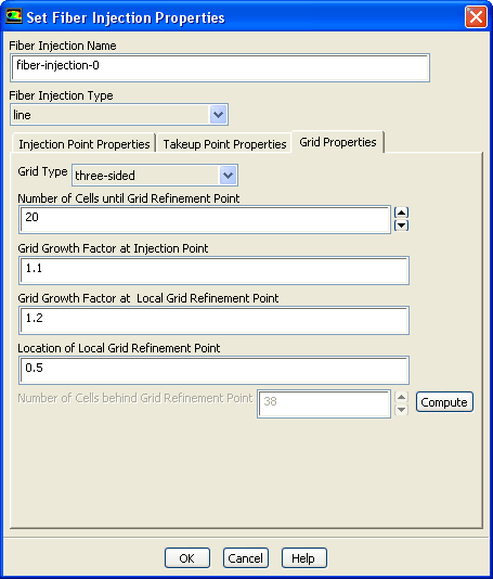
A three-sided grid consists of three sides where the fiber grid can be graded. The first side is near the injection point. The other two sides are around a refinement point within the fiber grid. Both sides at the refinement point are graded at the same ratio between the fiber grid cell lengths. To define a three-sided grid for the fibers, select three-sided from the Grid Type drop-down list (see Figure 3.6.10). Specify the Number of Cells until Grid Refinement Point, the Grid Growth Factor at Injection Point, and the Grid Growth Factor at Local Grid Refinement Point. You also have to specify the location of the grid refinement point in the Location of Local Grid Refinement Point field in a dimensionless way. The value you have to enter is relative to the fiber length and may be between 0 and 1. Values larger than 1 refine the grid, while values smaller than 1 coarsen the grid.
Click the Compute button to estimate the Number of Cells behind Grid Refinement Point.
 |
Previous:
3.6.7 Point Properties Specific



