![[ANSYS, Inc. Logo]](fluentlogo.gif)


|
|
|
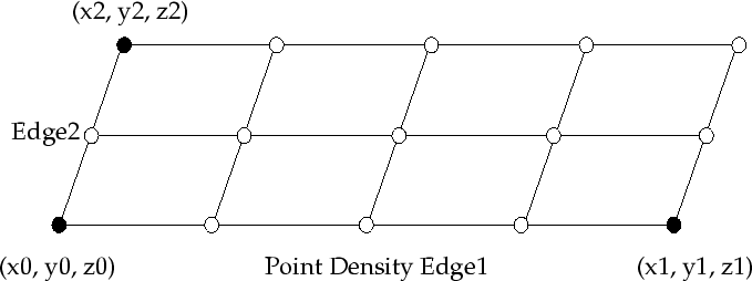
In a matrix fiber injection the starting points of the fibers are arranged in several rows having the shape of a rectangle or a parallelogram. Each row has the same distance to the previous and is divided into equal sections (see Figure 3.6.5).
You have to specify the coordinates of the starting point and the end of point of the first row and the coordinates where the last row should start. Click the
Injection Point Properties tab in the
Set Fiber Injection Properties dialog box (Figure
3.6.2). In the
Points region, set the
 ,
,
 , and
, and
 coordinates in the
x0,
y0, and
z0 fields for the starting point and the
coordinates in the
x0,
y0, and
z0 fields for the starting point and the
 ,
,
 , and
, and
 coordinates in the
x1,
y1, and
z1 fields for the end point of the first row of fibers. The
coordinates in the
x1,
y1, and
z1 fields for the end point of the first row of fibers. The
 ,
,
 , and
, and
 coordinates of the starting point of the last row have to be entered in the
x2,
y2, and
z2 fields.
coordinates of the starting point of the last row have to be entered in the
x2,
y2, and
z2 fields.
At each row, the number of fibers specified in the Point Density Edge1 field are injected. The number of rows to be injected is specified in Edge2.
You can double check the number of fibers computed in this fiber injection if you inspect the Numbers of Fibers Computed field.
|
|
Note that this fiber injection type is only available for 3D problems.
|
Previous:
3.6.6 Point Properties Specific