Once you have created an injection (using the
Fiber Injections dialog box, as described in Section
3.6.3), you will use the
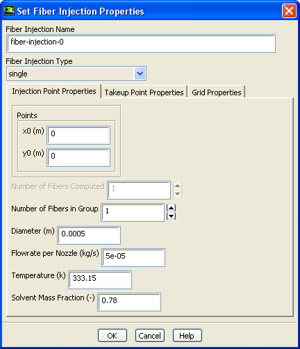
Set Fiber Injection Properties dialog box (Figure
3.6.2) to define the fiber injection properties. (Remember that this dialog box will open when you create a new fiber injection, or when you select an existing fiber injection and click the
Set... button in the
Fiber Injections dialog box.)
Figure 3.6.2: The
Set Fiber Injection Properties Dialog Box
The procedure for defining a fiber injection is as follows:
1.
If you want to change the name of the fiber injection from its default name, enter a new one in the
Fiber Injection Name field. This is recommended if you are defining a large number of injections so you can easily distinguish them.
2.
Choose the type of fiber injection in the
Fiber Injection Type drop-down list. The three choices (
single,
line, and
matrix) are described in Section
3.6.2.
3.
Click the
Injection Point Properties tab (the default), and specify the point coordinates according to the fiber injection type, as described in Sections
3.6.5-
3.6.7.
4.
If each of the defined fibers is referring to a group of fibers, enter the number of fibers in
Number of Fibers in Group. If your nozzle plate has 400 holes and you can simulate them as a line fiber injection with 5 groups, you have to enter a value of 80. This means that only 5 fibers are solved numerically, but each of these fibers stands for 80 fibers to be used to compute the source terms for the surrounding fluid. This allows you to reduce computing efforts while achieving a proper coupling with the surrounding fluid.
Note that the
Number of Fibers in Group is applied to all fibers, defined in your injection. If the number of fiber groups in your line or matrix injection is not the same for all fibers in this injection, you should split this injection into several fiber injections.
5.
Specify the diameter of the nozzle in the
Diameter field.
6.
Enter the mass flow rate for a single nozzle in the
Flowrate per Nozzle field. This will be used to compute the starting velocity of the fiber fluid.
Note that the value specified refers to one single nozzle and not to the mass flow rate of all fibers defined in this fiber injection.
7.
Specify the temperature of the fiber fluid leaving the nozzle in the
Temperature field.
8.
If you are modeling dry spun fibers you also have to enter the solvent's mass fraction at the nozzle in the
Solvent Mass Fraction field.
Figure 3.6.3: The
Set Fiber Injection Properties Dialog Box With Take-Up Point Properties
9.
Click the
Takeup Point Properties tab and enter the coordinates of the take-up point (see Figure
3.6.3).
Note that all fibers defined in the fiber injection are collected at the same point. If the fibers of your line or matrix injection vary in this property, you have to define them using several fiber injections.
10.
Select the appropriate boundary condition from the
Boundary Condition drop-down list and specify the value for this boundary condition. Choose
prescribed-velocity if you know the drawing or take-up velocity. Choose
tensile-force if you want to prescribe a given tensile force in the fiber at the take-up point.
11.
Click the
Grid Properties tab and enter all data needed to generate the fiber grid as described in Section
3.6.8.
![[ANSYS, Inc. Logo]](fluentlogo.gif)