![[ANSYS, Inc. Logo]](fluentlogo.gif)


|
|
|
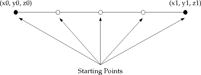
In a line fiber injection the starting points of the fibers are arranged on a line at a constant distance (see Figure
3.6.4). You have to specify the coordinates of the starting point and the end point of this line. Click the
Injection Point Properties tab in the
Set Fiber Injection Properties dialog box (Figure
3.6.2). In the
Points region, set the
 ,
,
 , and
, and
 coordinates in the
x0,
y0, and
z0 fields for the starting point of the line and the
coordinates in the
x0,
y0, and
z0 fields for the starting point of the line and the
 ,
,
 , and
, and
 coordinates in the
x1,
y1, and
z1 fields for the end point of the line. (
z0 and
z1 will appear only for 3D problems.)
coordinates in the
x1,
y1, and
z1 fields for the end point of the line. (
z0 and
z1 will appear only for 3D problems.)
In addition to the coordinates, you have to set the number of fibers defined in the line injection by entering the appropriate value in the Point Density Edge1 field. Please see Figure 3.6.4 for an example of a line fiber injection with a Point Density Edge1 of 5.
Previous:
3.6.5 Point Properties Specific