Step 2: General Settings
 General
- 1.
Check the mesh.
 General
 Check
Check
-
Note:
You should always make sure that the cell minimum volume is not negative, since
ANSYS FLUENT cannot begin a calculation if this is the case.
- 2.
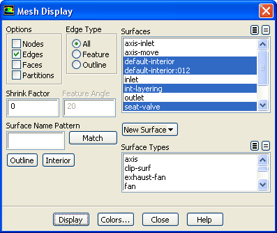
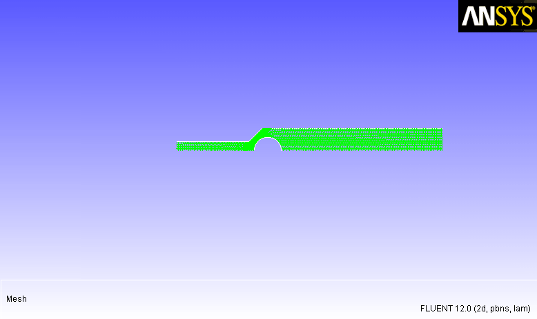
Display the mesh (Figure
13.2).
 General
 Display...
- (a)
Deselect
axis-inlet,
axis-move,
inlet, and
outlet from the
Surfaces selection list.
- (b)
Click
Display.
Figure 13.2: Initial Mesh for the Valve
 |
- (c)
Close the
Mesh Display dialog box.
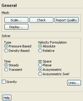
- 3.
Enable an axisymmetric steady-state calculation.
 General
- (a)
Select
Axisymmetric from the
2D Space list.


 Previous:
Step 1: Mesh
Previous:
Step 1: Mesh
Up:
Using Dynamic Meshes
Next:
Step 3: Models
Release 12.0 © ANSYS, Inc. 2009-02-09 ![[ANSYS, Inc. Logo]](fluentlogo.gif)