Dynamic mesh motion and all related parameters are specified using the items in the
Dynamic Mesh task page, not through the
Boundary Conditions task page. You will set these conditions in a later step.
1.
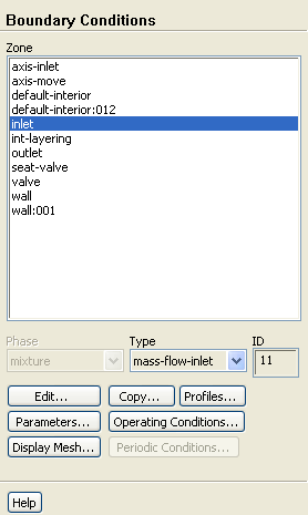
Set the conditions for the mass flow inlet (
inlet).
Boundary Conditionsinlet
Since the inlet boundary is assigned to a wall boundary type in the original mesh, you will need to explicitly assign the inlet boundary to a mass flow inlet boundary type in
ANSYS FLUENT.
(a)
Select
mass-flow-inlet from the
Type drop-down list in the
Boundary Conditions task page.
(b)
Click
Yes when
ANSYS FLUENT asks you if you want to change the zone type.
The
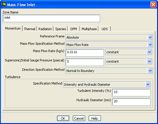
Mass-Flow Inlet boundary condition dialog box will open.
i.
Enter
0.0116 kg/s for
Mass Flow Rate.
ii.
Select
Normal to Boundary from the
Direction Specification Method drop-down list.
iii.
Select
Intensity and Hydraulic Diameter from the
Specification Method drop-down list in the
Turbulence group box.
iv.
Retain
10 % for
Turbulent Intensity.
v.
Enter
20 mm for the
Hydraulic Diameter.
vi.
Click
OK to close the
Mass-Flow Inlet dialog box.
2.
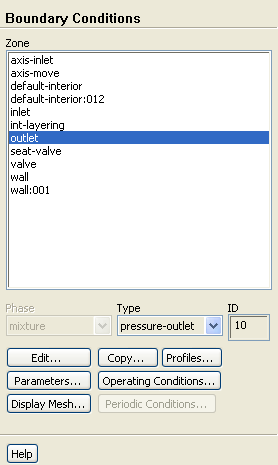
Set the conditions for the exit boundary (
outlet).
Boundary Conditionsoutlet
Since the
outlet boundary is assigned to a wall boundary type in the original mesh, you will need to explicitly assign the outlet boundary to a pressure outlet boundary type in
ANSYS FLUENT.
(a)
Select
pressure-outlet from the
Type drop-down list in the
Boundary Conditions task page.
(b)
Click
Yes when
ANSYS FLUENT asks you if you want to change the zone type.
The
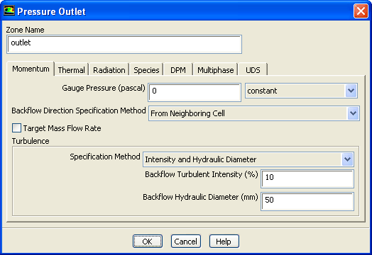
Pressure Outlet boundary condition dialog box will open.
i.
Select
From Neighboring Cell from the
Backflow Direction Specification Method drop-down list.
ii.
Select
Intensity and Hydraulic Diameter from the
Specification Method drop-down list in the
Turbulence group box.
iii.
Retain
10 % for
Turbulent Intensity.
iv.
Enter
50 mm for
Backflow Hydraulic Diameter.
v.
Click
OK to close the
Pressure Outlet dialog box.
3.
Set the boundary type to
axis for both the
axis-inlet and the
axis-move boundaries.
Boundary Conditions
Since the
axis-inlet and the
axis-move boundaries are assigned to a wall boundary type in the original mesh, you will need to explicitly assign these boundaries to an axis boundary type in
ANSYS FLUENT.
(a)
Select
axis-inlet from the
Zone list and select
axis from the
Type list.
(b)
Click
Yes when
ANSYS FLUENT asks you if you want to change the zone type.
(c)
Retain the default
Zone Name in the
Axis dialog box and click
OK to close the
Axis dialog box.
(d)
Select
axis-move from the
Zone list and select
axis from the
Type list.
(e)
Click
Yes when
ANSYS FLUENT asks you if you want to change the zone type.
(f)
Retain the default
Zone Name in the
Axis dialog box and click
OK to close the
Axis dialog box.
![[ANSYS, Inc. Logo]](fluentlogo.gif)


 Boundary Conditions
 Boundary Conditions

 inlet
inlet
 Boundary Conditions

 outlet
 Boundary Conditions