- 1.
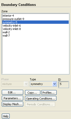
Convert the symmetry zone to the axis type.
 Boundary Conditions

 symmetry-5
-
The symmetry zone must be converted to an axis to prevent numerical difficulties where the radius reduces to zero.
- (a)
Select
axis from the
Type drop-down list.
-
A
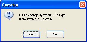
Question dialog box will open, asking if it is OK to change the type of
symmetry-5 from symmetry to axis. Click
Yes to continue.
-
The
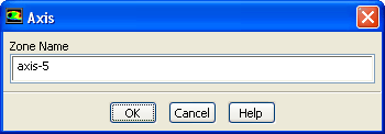
Axis dialog box will open and display the default name for the newly created axis zone. Click
OK to continue.
- 2.
Set the boundary conditions for the air inlet (
velocity-inlet-8).
 Boundary Conditions

 velocity-inlet-8
 Edit...
-
To determine the zone for the air inlet, display the mesh without the fluid zone to see the boundaries. Use the right mouse button to probe the air inlet.
ANSYS FLUENT will report the zone name (
velocity-inlet-8) in the console.
- (a)
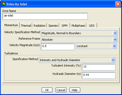
Enter
air-inlet for
Zone Name.
-
This name is more descriptive for the zone than
velocity-inlet-8.
- (b)
Enter
0.5
 for
Velocity Magnitude.
for
Velocity Magnitude.
- (c)
Select
Intensity and Hydraulic Diameter from the
Specification Method drop-down list in the
Turbulence group box.
- (d)
Retain the default value of
10
 for
Turbulent Intensity.
for
Turbulent Intensity.
- (e)
Enter
0.44
 for
Hydraulic Diameter.
for
Hydraulic Diameter.
- (f)
Click the
Thermal tab and retain the default value of
300
 for
Temperature.
for
Temperature.
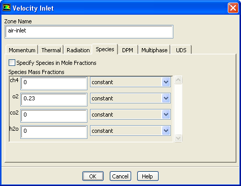
- (g)
Click the
Species tab and enter
0.23 for
o2 in the
Species Mass Fractions group box.
- (h)
Click
OK to close the
Velocity Inlet dialog box.
- 3.
Set the boundary conditions for the fuel inlet (
velocity-inlet-6).
 Boundary Conditions

 velocity-inlet-6
 Edit...
- (a)
Enter
fuel-inlet for
Zone Name.
-
This name is more descriptive for the zone than
velocity-inlet-6.
- (b)
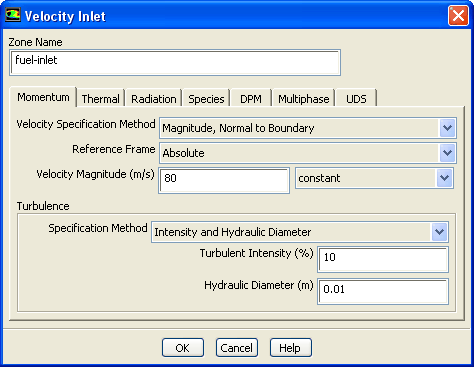
Enter
80
 for the
Velocity Magnitude.
for the
Velocity Magnitude.
- (c)
Select
Intensity and Hydraulic Diameter from the
Specification Method drop-down list in the
Turbulence group box.
- (d)
Retain the default value of
10
 for
Turbulent Intensity.
for
Turbulent Intensity.
- (e)
Enter
0.01
 for
Hydraulic Diameter.
for
Hydraulic Diameter.
- (f)
Click the
Thermal tab and retain the default value of
300
 for
Temperature.
for
Temperature.
- (g)
Click the
Species tab and enter
1 for
ch4 in the
Species Mass Fractions group box.
- (h)
Click
OK to close the
Velocity Inlet dialog box.
- 4.
Set the boundary conditions for the exit boundary (
pressure-outlet-9).
 Boundary Conditions

 pressure-outlet-9
 Edit...
- (a)
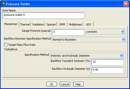
Retain the default value of
0
 for
Gauge Pressure.
for
Gauge Pressure.
- (b)
Select
Intensity and Hydraulic Diameter from the
Specification Method drop-down list in the
Turbulence group box.
- (c)
Retain the default value of
10
 for
Backflow Turbulent Intensity.
for
Backflow Turbulent Intensity.
- (d)
Enter
0.45
 for
Backflow Hydraulic Diameter.
for
Backflow Hydraulic Diameter.
- (e)
Click the
Thermal tab and retain the default value of
300
 for
Backflow Total Temperature.
for
Backflow Total Temperature.
- (f)
Click the
Species tab and enter
0.23 for
o2 in the
Species Mass Fractions group box.
- (g)
Click
OK to close the
Pressure Outlet dialog box.
-
The
Backflow values in the
Pressure Outlet dialog box are utilized only when backflow
occurs at the pressure outlet. Always assign reasonable values because backflow may occur during intermediate iterations and could affect the solution stability.
- 5.
Set the boundary conditions for the outer wall (
wall-7).
 Boundary Conditions

 wall-7
 Edit...
-
Use the mouse-probe method described for the air inlet to determine the zone corresponding to the outer wall.
- (a)
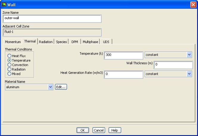
Enter
outer-wall for
Zone Name.
-
This name is more descriptive for the zone than
wall-7.
- (b)
Click the
Thermal tab.
- i.
Select
Temperature in the
Thermal Conditions list.
- ii.
Retain the default value of
300
 for
Temperature.
for
Temperature.
- (c)
Click
OK to close the
Wall dialog box.
- 6.
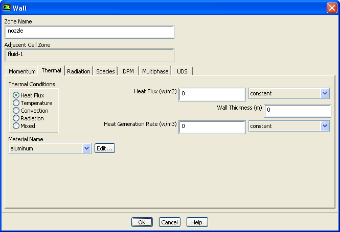
Set the boundary conditions for the fuel inlet nozzle (
wall-2).
 Boundary Conditions

 wall-2
 Edit...
- (a)
Enter
nozzle for
Zone Name.
-
This name is more descriptive for the zone than
wall-2.
- (b)
Click the
Thermal tab.
- i.
Retain the default selection of
Heat Flux in the
Thermal Conditions list.
- ii.
Retain the default value of
0
 for
Heat Flux, so that the wall is adiabatic.
for
Heat Flux, so that the wall is adiabatic.
- (c)
Click
OK to close the
Wall dialog box.
![[ANSYS, Inc. Logo]](fluentlogo.gif)


 Boundary Conditions