- 1.
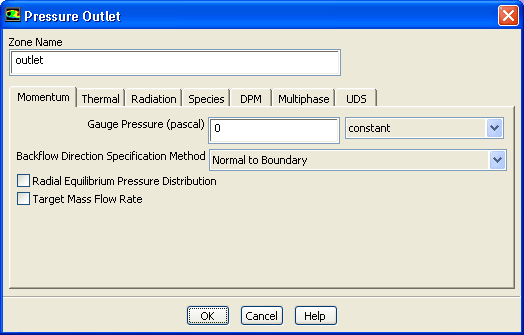
Retain the default settings for
outlet.
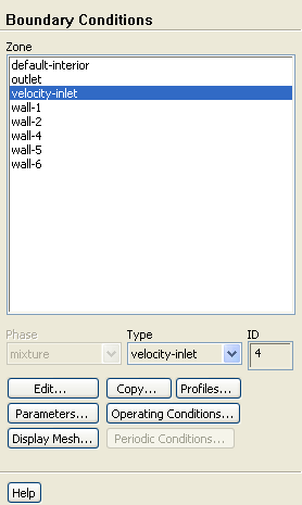
 Boundary Conditions

 outlet
 Edit...
- 2.
Set the conditions for
velocity-inlet.
 Boundary Conditions

 velocity-inlet
 Edit...
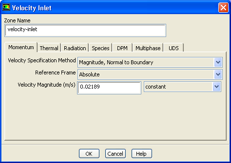
- (a)
Retain the default selection of
Magnitude, Normal to Boundary from the
Velocity Specification Method drop-down list.
- (b)
Retain the default selection of
Absolute from the
Reference Frame drop-down list.
- (c)
Enter
0.02189 m/s for
Velocity Magnitude.
- (d)
Click the
Thermal tab and enter
293 K for
Temperature.
- (e)
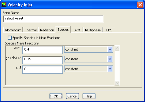
Click the
Species tab.
- i.
Set the
Species Mass Fractions for
ash3 to
0.4,
ga
 ch3
ch3
 3 to
0.15, and
ch3 to
0 respectively.
3 to
0.15, and
ch3 to
0 respectively.
- (f)
Click
OK to close the
Velocity Inlet dialog box.
- 3.
Set the boundary conditions for
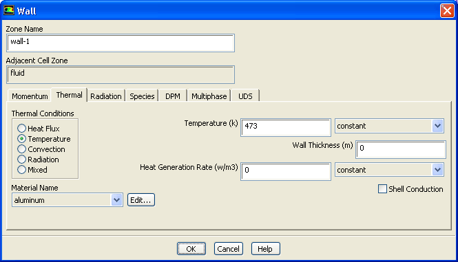
wall-1.
 Boundary Conditions

 wall-1
 Edit...
- (a)
Click the
Thermal tab.
- i.
Select
Temperature in the
Thermal Conditions group box.
- ii.
Enter
473 K for
Temperature.
- (b)
Click
OK to close the
Wall dialog box.
- 4.
Set the boundary conditions for
wall-2.
 Boundary Conditions

 wall-2
 Edit...
- (a)
Click the
Thermal tab.
- i.
Select
Temperature in the
Thermal Conditions group box.
- ii.
Enter
343 K for
Temperature.
- (b)
Click
OK to close the
Wall dialog box.
- 5.
Set the boundary conditions for
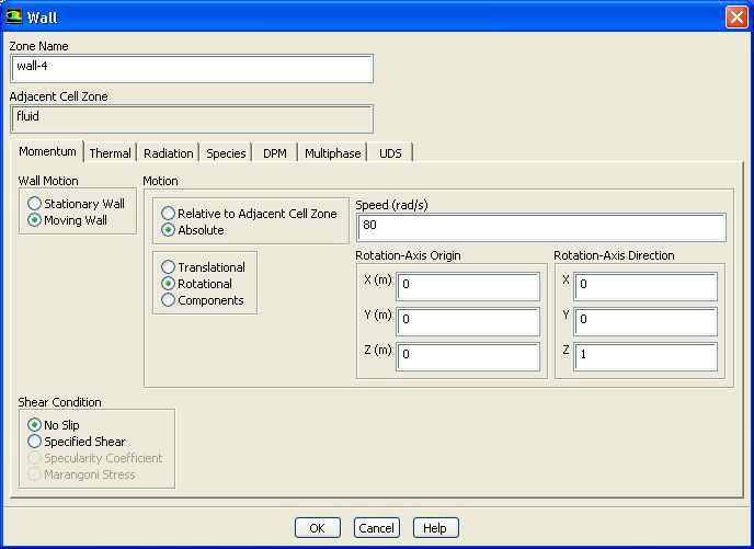
wall-4.
 Boundary Conditions

 wall-4
 Edit...
- (a)
Select
Moving Wall in the
Wall Motion group box.
- (b)
Select
Absolute and
Rotational in the
Motion group box.
- (c)
Enter
80 rad/s for
Speed.
- (d)
Retain the other default settings.
- (e)
Click the
Thermal tab.
- i.
Select
Temperature in the
Thermal Conditions group box.
- ii.
Enter
1023 K for
Temperature.
- (f)
Click the
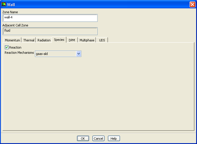
Species tab.
- i.
Enable
Reaction.
- ii.
Retain the selection of
gaas-ald from the
Reaction Mechanisms drop-down list.
- (g)
Click
OK to close the
Wall dialog box.
- 6.
Set the boundary conditions for
wall-5.
 Boundary Conditions

 wall-5
 Edit...
- (a)
Select
Moving Wall in the
Wall Motion group box.
- (b)
Select
Absolute and
Rotational in the
Motion group box.
- (c)
Enter
80 rad/s for
Speed.
- (d)
Click the
Thermal tab.
- i.
Select
Temperature in the
Thermal Conditions group box.
- ii.
Enter
720 K for
Temperature.
- (e)
Click
OK to close the
Wall dialog box.
- 7.
Set the boundary conditions for
wall-6.
 Boundary Conditions

 wall-6
 Edit...
- (a)
Click the
Thermal tab.
- i.
Select
Temperature in the
Thermal Conditions group box.
- ii.
Enter
303 K for
Temperature.
- (b)
Click
OK to close the
Wall dialog box.
- 8.
Disable diffusion at the inlet.
 Models

 Species
 Edit...
- (a)
Disable
Inlet Diffusion and close the
Species Model dialog box.
-
You can also use the
define/models/species/inlet-diffusion? text command to disable inlet diffusion. Enter
no when asked if you want to include diffusion at the inlet.
![[ANSYS, Inc. Logo]](fluentlogo.gif)


 Boundary Conditions