- 1.
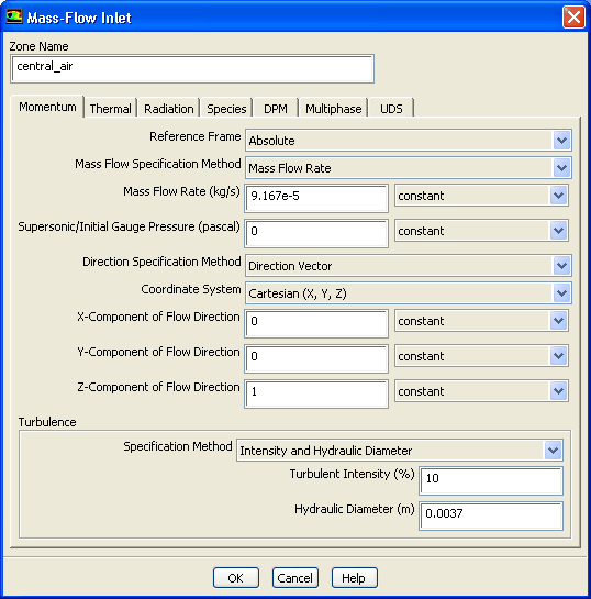
Set the boundary conditions for the inner air stream (
central_air).
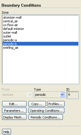
 Boundary Conditions

 central_air
 Edit...
- (a)
Enter
9.167e-5 kg/s for
Mass Flow Rate.
- (b)
Enter
0 for both
X-Component of Flow Direction and
Y-Component of Flow Direction.
- (c)
Enter
1 for
Z-Component of Flow Direction.
- (d)
Select
Intensity and Hydraulic Diameter from the
Specification Method drop-down list.
- (e)
Retain the default value of
10 for
Turbulent Intensity.
- (f)
Enter
0.0037 m for
Hydraulic Diameter.
- (g)
Click the
Thermal tab and enter
293 K for
Total Temperature.
- (h)
Click the
Species tab and enter
0.23 for
o2 in the
Species Mass Fractions group box.
- (i)
Click
OK to close the
Mass-Flow Inlet dialog box.
- 2.
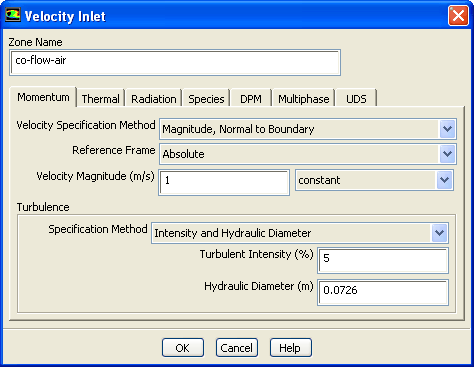
Set the boundary conditions for the air stream surrounding the atomizer
(
co-flow-air).
 Boundary Conditions

 co-flow-air
 Edit...
- (a)
Enter
1 m/s for
Velocity Magnitude.
- (b)
Select
Intensity and Hydraulic Diameter from the
Specification Method drop-down list.
- (c)
Enter
5 for
Turbulent Intensity.
- (d)
Enter
0.0726 m for
Hydraulic Diameter.
- (e)
Click the
Thermal tab and enter
293 K for
Temperature.
- (f)
Click the
Species tab and enter
0.23 for
o2 in the
Species Mass Fractions group box.
- (g)
Click
OK to close the
Velocity Inlet dialog box.
- 3.
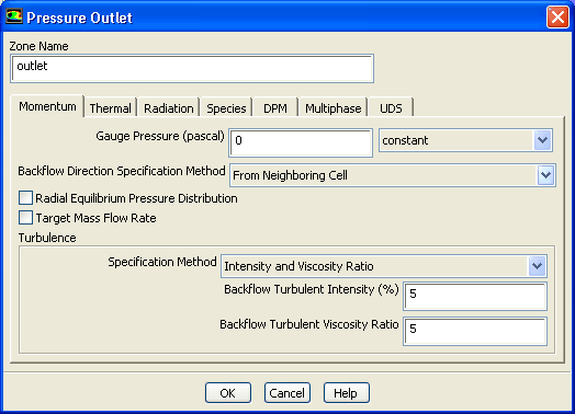
Set the boundary conditions for the exit boundary (
outlet).
 Boundary Conditions

 outlet
 Edit...
- (a)
Select
From Neighboring Cell from the
Backflow Direction Specification Method drop-down list.
- (b)
Select
Intensity and Viscosity Ratio from the
Specification Method drop-down list.
- (c)
Enter
5 for both
Backflow Turbulent Intensity and
Backflow Turbulent Viscosity Ratio.
- (d)
Click the
Thermal tab and enter
293 K for
Backflow Total Temperature.
- (e)
Click the
Species tab and enter
0.23 for
o2 in the
Species Mass Fractions group box.
- (f)
Click
OK to close the
Pressure Outlet dialog box.
- 4.
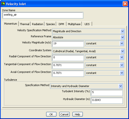
Set the boundary conditions for the swirling annular stream (
swirling_air).
 Boundary Conditions

 swirling_air
 Edit...
- (a)
Select
Magnitude and Direction from the
Velocity Specification Method drop-down list.
- (b)
Enter
19 m/s for
Velocity Magnitude.
- (c)
Select
Cylindrical (Radial, Tangential, Axial) from the
Coordinate System drop-down list.
- (d)
Enter
0 for
Radial-Component of Flow Direction.
- (e)
Enter
0.7071 for both
Tangential-Component of Flow Direction and
Axial-Component of Flow Direction.
- (f)
Select
Intensity and Hydraulic Diameter from the
Specification Method drop-down list.
- (g)
Enter
5 for
Turbulent Intensity.
- (h)
Enter
0.0043 m for
Hydraulic Diameter.
- (i)
Click the
Thermal tab and enter
293 K for
Temperature.
- (j)
Click the
Species tab and enter
0.23 for
o2 in the
Species Mass Fractions group box.
- (k)
Click
OK to close the
Velocity Inlet dialog box.
- 5.
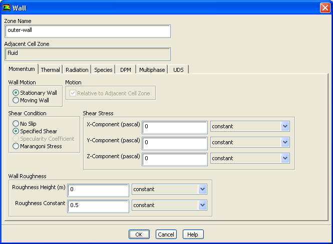
Set the boundary conditions for the outer wall of the atomizer (
outer-wall).
 Boundary Conditions

 outer-wall
 Edit...
- (a)
Select
Specified Shear in the
Shear Condition list.
- (b)
Retain the default values for the remaining parameters.
- (c)
Click
OK to close the
Wall dialog box.
![[ANSYS, Inc. Logo]](fluentlogo.gif)


 Boundary Conditions