[ANSYS, Inc. Logo] return to home search
next up previous contents

Step 7: Create a Spray Injection

1.   Define the discrete phase modeling parameters.

figure Models figure figure Discrete Phase figure Edit...

figure

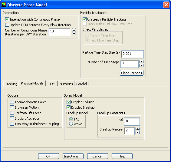
(a)   Enable Interaction with Continuous Phase in the Interaction group box.

  This will include the effects of the discrete phase trajectories on the continuous phase.

(b)   Retain the value of 10 for Number of Continuous Phase Iterations per DPM Iteration.

(c)   Click the Physical Models tab to enable the physical models.

i.   Enable Droplet Collision and Droplet Breakup in the Spray Model group box.

ii.   Ensure that TAB is enabled in the Breakup Model list.

iii.   Retain the default value of 0 for y0 and 2 for Breakup Parcels in the Breakup Constants group box.

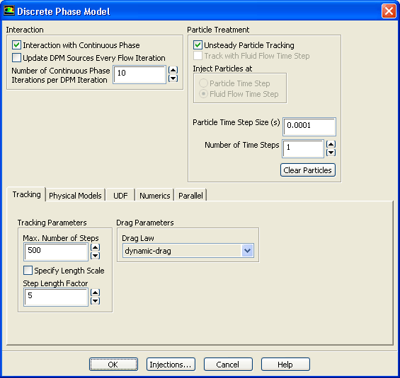
(d)   Click the Tracking tab to specify the Tracking Parameters.

figure

i.   Retain the default value of 5 for Step Length Factor.

ii.   Select dynamic-drag from the Drag Law drop-down list in the Drag Parameters group box.

  The dynamic-drag law is available only when the Droplet Breakup model is used.

(e)   Retain the Unsteady Particle Tracking option in the Particle Treatment group box.

(f)   Enter 0.0001 for Particle Time Step Size.

(g)   Retain the default value of 1 for Number of Time Steps.

(h)   Click OK to close the Discrete Phase Model dialog box.

  An Information dialog box will open, stating that coalescence is being automatically switched off.

(i)   Click OK in the Information dialog box to proceed.

2.   Create the spray injection.

  In this step, you will define the characteristics of the atomizer.

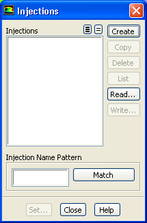
Define $\rightarrow$ Injections...

figure

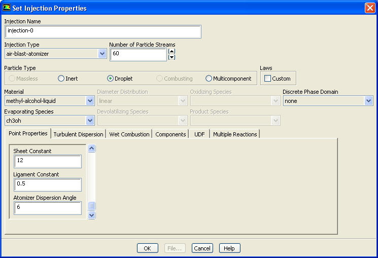
(a)   Click the Create button to open the Set Injection Properties dialog box.

figure

(b)   Select air-blast-atomizer from the Injection Type drop-down list.

(c)   Enter 60 for Number of Particle Streams.

  This option controls the number of droplet parcels that are introduced into the domain at every time step.

(d)   Select Droplet in the Particle Type group box.

(e)   Select methyl-alcohol-liquid from the Material drop-down list.

(f)   Enter 0, 0, and 0.0015 for X-Position, Y-Position, and Z-Position, respectively, in the Point Properties tab.

  Scroll down the list to see the remaining point properties.

(g)   Retain the default values of 0, 0, and 1 for X-Axis, Y-Axis, and Z-Axis, respectively.

(h)   Enter 263 K for Temperature.

(i)   Enter 8.5e-5 kg/s for Flow Rate.

  This is the methanol flow rate for a 30-degree section of the atomizer. The actual atomizer flow rate is 12 times this value.

(j)   Retain the default Start Time of 0 s and enter 100 s for the Stop Time.

  For this problem, the injection should begin at $t=0$ and not stop until long after the time period of interest. A large value for the stop time (e.g., 100 s) will ensure that the injection will essentially never stop.
(k)   Enter 0.0035 m for the Injector Inner Diameter and 0.0045 m for the Injector Outer Diameter.

(l)   Enter -45 degrees for Spray Half Angle.

  The spray angle is the angle between the liquid sheet trajectory and the injector centerline. In this case, the value is negative because the sheet is initially converging toward the centerline.

(m)   Enter 82.6 m/s for the Relative Velocity.

  The relative velocity is the expected relative velocity between the atomizing air and the liquid sheet.

(n)   Retain the default Azimuthal Start Angle of 0 degrees and enter 30 degrees for the Azimuthal Stop Angle.

  This will restrict the injection to the 30-degree section of the atomizer that is being modeled.

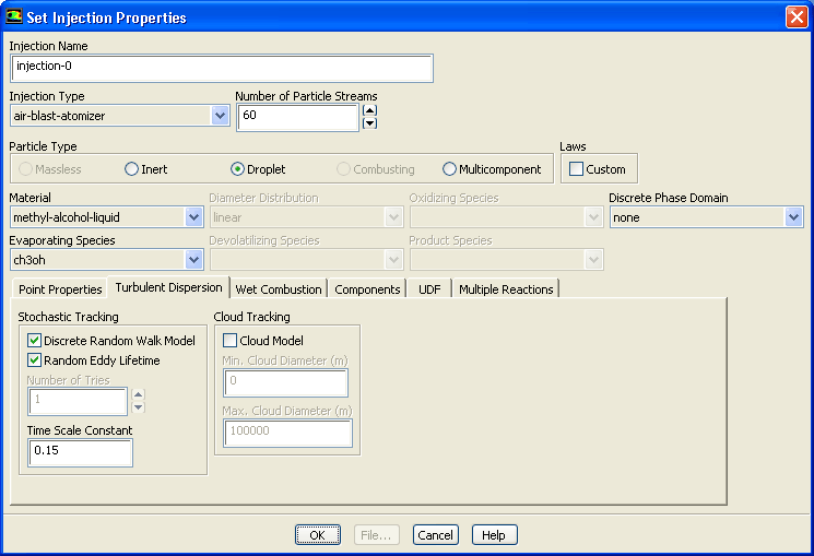
(o)   Define the turbulent dispersion.
i.   Click the Turbulent Dispersion tab.

figure

  The lower half of the dialog box will change to show options for the turbulent dispersion model.

ii.   Enable Discrete Random Walk Model and Random Eddy Lifetime in the Stochastic Tracking group box.

  These models will account for the turbulent dispersion of the droplets.

(p)   Click OK to close the Set Injection Properties dialog box.

(q)   Click OK in the Information dialog box to enable droplet coalescence.

(r)   Close the Injections dialog box.

Note:   In the case that the spray injection would be striking a wall, you should specify the wall boundary conditions for the droplets. Though this tutorial does have wall zones, they are a part of the atomizer apparatus. You need not change the wall boundary conditions any further because these walls are not in the path of the spray droplets.

3.   Set the droplet material properties.

figure Materials figure figure methyl-alcohol-liquid figure Create/Edit...

  Set the droplet properties because secondary atomization models (breakup and coalescence) are used.

figure

(a)   Retain the default selection of droplet-particle from the Material Type drop-down list.

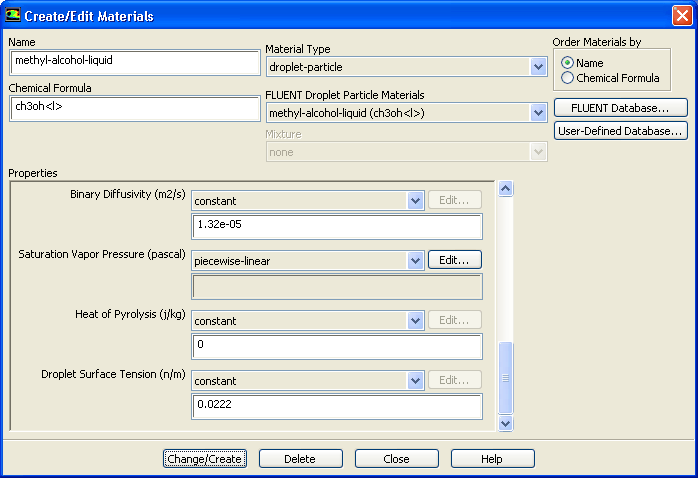
(b)   Enter 0.0056 kg/m-s for Viscosity in the Properties group box.

(c)   Select piecewise-linear from the Saturation Vapor Pressure drop-down list.

  Scroll down to find the Saturation Vapor Pressure drop-down list.

The Piecewise-Linear Profile dialog box will open.

i.   Click OK to retain the default values and close the Piecewise-Linear Profile dialog box.

(d)   Scroll down and enter 0.0222 N/m for Droplet Surface Tension.

(e)   Click Change/Create to accept the change in properties for the methanol droplet material and close the Create/Edit Materials dialog box.


next up previous contents Previous: Step 6: Initial Solution
Up: Modeling Evaporating Liquid Spray
Next: Step 8: Solution
Release 12.0 © ANSYS, Inc. 2009-02-09