[ANSYS, Inc. Logo] return to home search
next up previous contents

Step 8: Solution

1.   Decrease the Under-Relaxation Factor for Discrete Phase Sources to 0.1.

figure Solution Controls

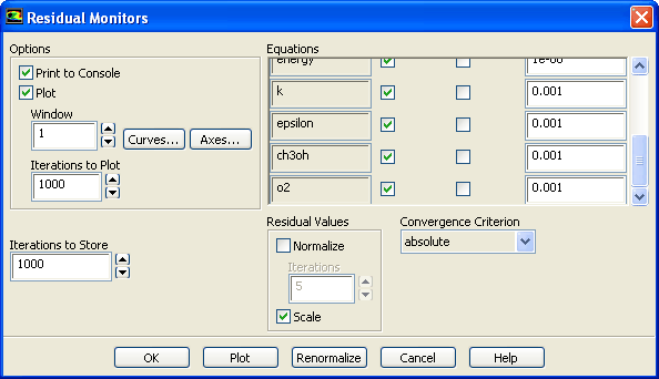
2.   Disable Check Convergence for all the residuals.

figure Monitors figure figure Residuals figure Edit...

figure

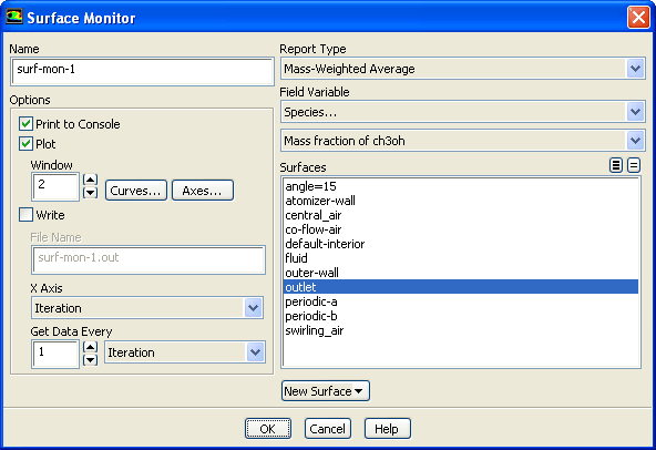
3.   Enable the plotting of mass fraction of ch3oh.

figure Monitors (Surface Monitors) figure Create...

figure

(a)   Retain surf-mon-1 for Name.

(b)   Enable Plot.

(c)   Select Mass-Weighted Average from the Report Type drop-down list.

(d)   Select Species... and Mass fraction of ch3oh from the Field Variable drop-down lists.

(e)   Select outlet from the Surfaces selection list.

(f)   Click OK to close the Surface Monitor dialog box.

4.   Enable the plotting of the sum of the DPM Mass Source.

figure Monitors (Volume Monitors) figure Create...

figure

(a)   Retain vol-mon-1 for Name.

(b)   Enable Plot.

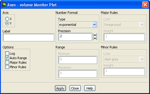
(c)   Click the Axes... button to open the Axes - volume Monitor Plot dialog box.

figure

i.   Select Y in the Axis list.

ii.   Select exponential from the Type drop-down list.

iii.   Set Precision to 2.

iv.   Click Apply and close the Axes - volume Monitor Plot dialog box.

(d)   Select Sum from the Report Type drop-down list.

(e)   Select Discrete Phase Model... and DPM Mass Source from the Field Variable drop-down lists.

(f)   Select fluid from the Cell Zones selection list.

(g)   Click OK to close the Volume Monitor dialog box.

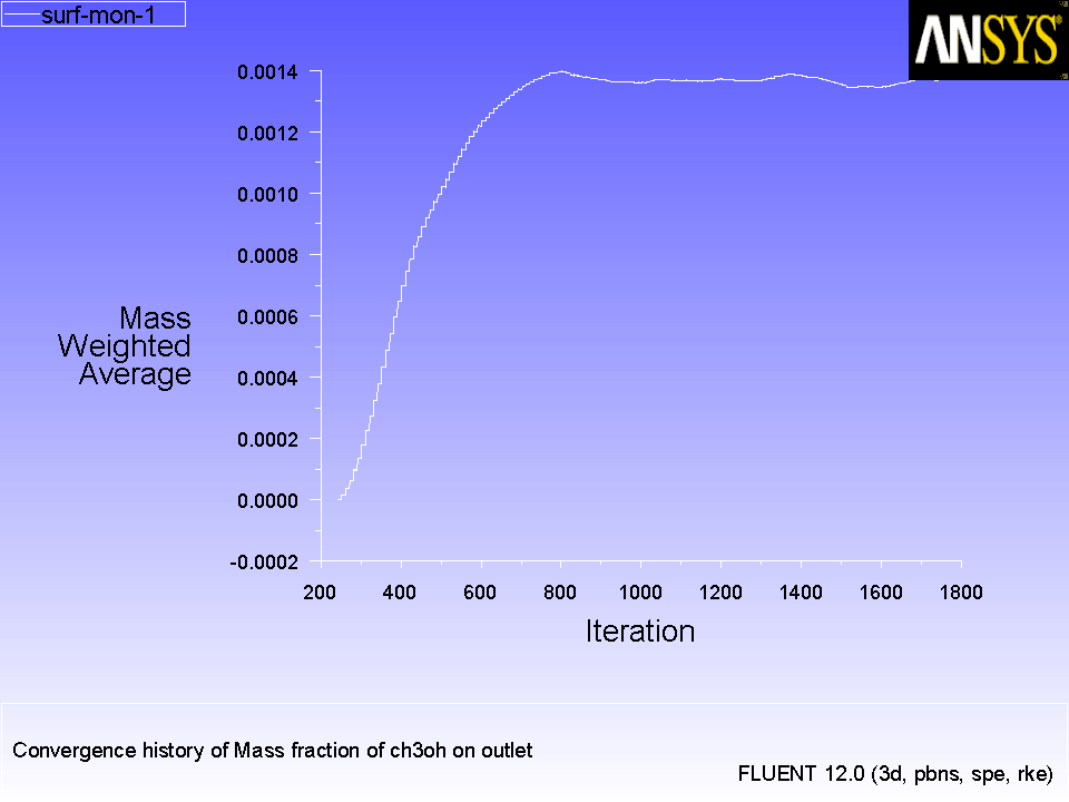
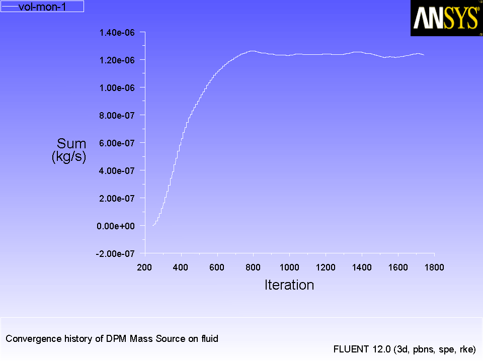
5.   Request 1500 more iterations (Figures  17.5 and 17.6).

figure Run Calculation

  It can be concluded that the solution is converged because the number of particle tracks are constant and the monitors are flat.

Figure 17.5: Convergence History of Mass Fraction of ch3oh on Fluid
figure

Figure 17.6: Convergence History of DPM Mass Source on Fluid
figure

6.   Save the case and data files ( spray2.cas.gz and spray2.dat.gz).

File $\rightarrow$ Write $\rightarrow$ Case & Data...

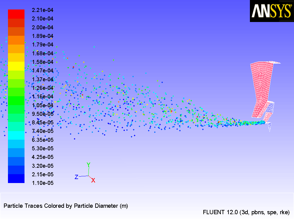
7.   Display the trajectories of the droplets in the spray injection (Figure  17.7).

  This will allow you to review the location of the droplets.

figure Graphics and Animations figure figure Particle Tracks figure Set Up...

figure

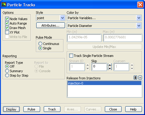
(a)   Enable Draw Mesh in the Options group box.

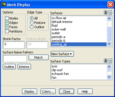
  The Mesh Display dialog box will open.

figure

i.   Retain the current display settings.

ii.   Close the Mesh Display dialog box.

(b)   Retain the default selection of point from the Style drop-down list.

(c)   Select Particle Variables... and Particle Diameter from the Color by drop-down lists.

  This will display the location of the droplets colored by their diameters.

(d)   Select injection-0 from the Release from Injections selection list.

(e)   Click Display and close the Particle Tracks dialog box.

(f)   Restore the 30-degree section to obtain the view as shown in Figure  17.7.
figure Graphics and Animations figure Views...
i.   Click the Define button to open Graphics Periodicity dialog box.

ii.   Click Reset and close the Graphics Periodicity dialog box.

iii.   Close the Views dialog box.

(g)   Use the mouse to obtain the view shown in Figure  17.7.

Figure 17.7: Particle Tracks for the Spray Injection After 200 Iterations
figure

  The air-blast atomizer model assumes that a cylindrical liquid sheet exits the atomizer, which then disintegrates into ligaments and droplets. Appropriately, the model determines that the droplets should be input into the domain in a ring. The radius of this disk is determined from the inner and outer radii of the injector.

Note:   The maximum diameter of the droplets is about $10^{-4}$ m or 0.1 mm. This is slightly smaller than the film height. The inner diameter and outer diameter of the injector are 3.5 mm and 4.5 mm, respectively. Hence the film height is $0.5$ mm. The range in the droplet sizes is due to the fact that the air-blast atomizer automatically uses a distribution of droplet sizes.

Also note that the droplets are placed a slight distance away from the injector. Once the droplets are injected into the domain, they can collide/coalesce with other droplets as determined by the secondary models (breakup and collision). However, once a droplet has been introduced into the domain, the air-blast atomizer model no longer affects the droplet.


next up previous contents Previous: Step 7: Create a
Up: Modeling Evaporating Liquid Spray
Next: Step 9: Postprocessing
Release 12.0 © ANSYS, Inc. 2009-02-09