A warning message will be displayed twice in the console. You need not take any action at this point, as the issue will be resolved when you define the solver settings in Step 2.
Extra:
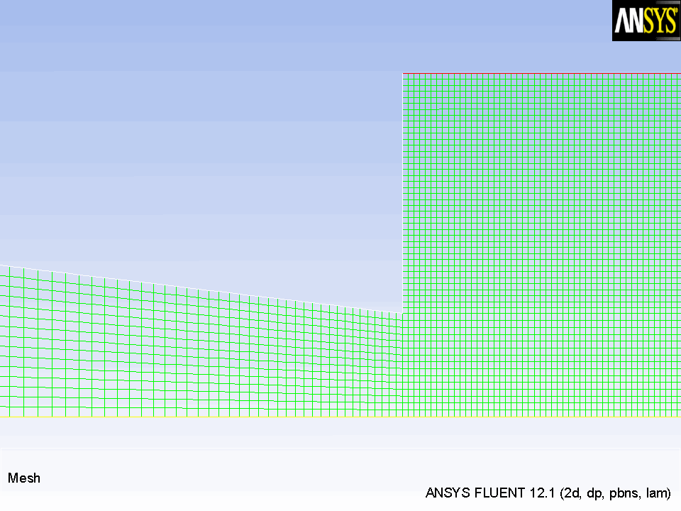
By zooming in with the middle mouse button, you can see that the interior of the model is composed of a fine mesh of quadrilateral cells (see Figure
18.3).
Figure 18.3: The Quadrilateral Mesh
3.
Manipulate the mesh display to show the full chamber upright.
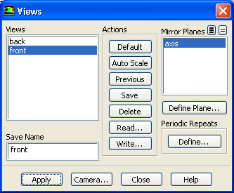
Graphics and AnimationsViews...
(a)
Select
front from the
Views selection list.
(b)
Select
axis from the
Mirror Planes selection list.
(c)
Click
Apply.
The mesh display will be updated to show both sides of the chamber.
(d)
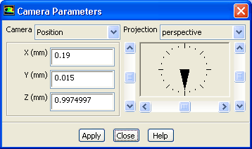
Click the
Camera... button to open the
Camera Parameters dialog box.
i.
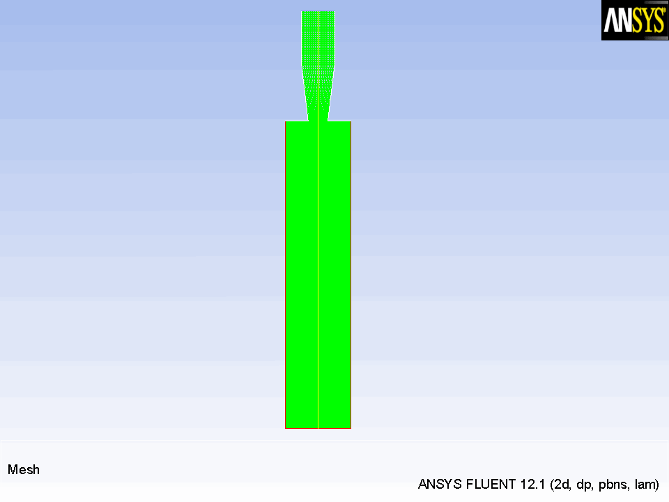
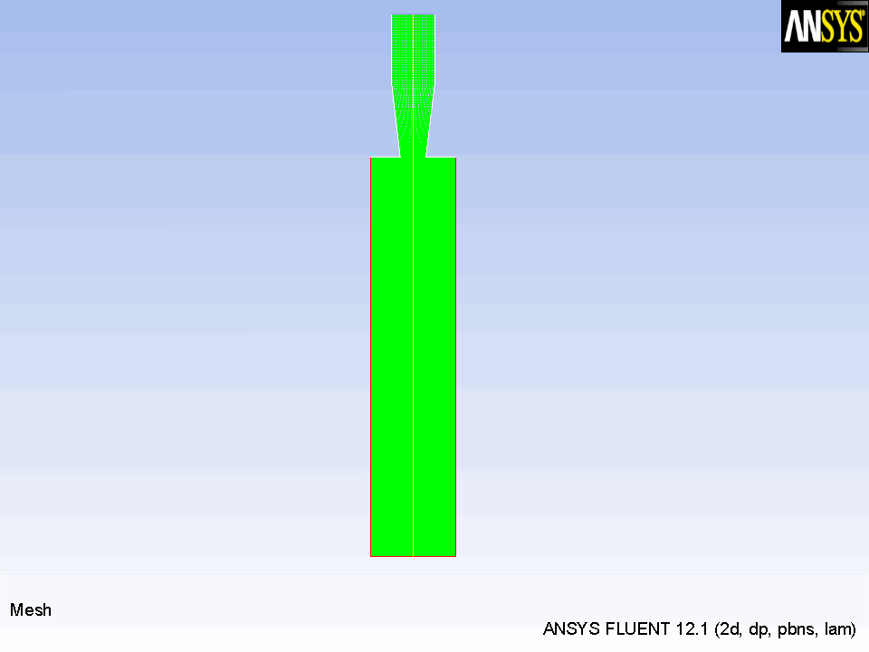
Drag the indicator of the dial with the left mouse button in the clockwise direction until the upright view is displayed (Figure
18.4).
Figure 18.4: Mesh Display of the Nozzle Mirrored and Upright
![[ANSYS, Inc. Logo]](fluentlogo.gif)


 Read
Read
 Mesh..
 Graphics and Animations
 Views...