In the following steps, you will define water as the secondary phase. When you define the initial solution, you will patch water in the nozzle region. In general, you can specify the primary and secondary phases whichever way you prefer. It is a good idea to consider how your choice will affect the ease of problem setup, especially with more complicated problems.
1.
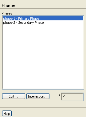
Specify air (
air) as the primary phase.
Phasesphase-1 - Primary PhaseEdit...
(a)
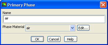
Enter
air for
Name.
(b)
Retain the default selection of
air in the
Phase Material drop-down list.
(c)
Click
OK to close the
Primary Phase dialog box.
2.
Specify water (
water-liquid) as the secondary phase.
Phasesphase-2 - Secondary PhaseEdit...
(a)
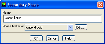
Enter
water-liquid for
Name.
(b)
Select
water-liquid from the
Phase Material drop-down list.
(c)
Click
OK to close the
Secondary Phase dialog box.
3.
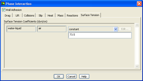
Specify the interphase interaction.
PhasesInteraction...
(a)
Enable
Wall Adhesion so that contact angles can be prescribed.
(b)
Click the
Surface Tension tab.
The surface tension coefficient inputs will be displayed.
i.
Select
constant from the
Surface Tension Coefficient drop-down list.
ii.
Enter
73.5 dyn/cm for
Surface Tension Coefficient.
(c)
Click
OK to close the
Phase Interaction dialog box.
![[ANSYS, Inc. Logo]](fluentlogo.gif)


 Phases
 Phases

 phase-1 - Primary Phase
 Edit...
 Phases

 phase-2 - Secondary Phase
 Edit...
 Phases
 Interaction...