Step 6: Operating Conditions
Boundary Conditions
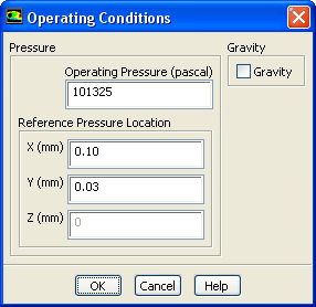
1. Set the operating reference pressure location.
Boundary Conditions
Operating Conditions...
You will set the
Reference Pressure Location
to be a point where the fluid will always be 100
air.
(a) Enter
0.10
mm for
X
.
(b) Enter
0.03
mm for
Y
.
(c) Click
OK
to close the
Operating Conditions
dialog box.
Previous:
Step 5: Phases
Up:
Using the VOF Model
Next:
Step 7: User-Defined Function
Release 12.1 ©
ANSYS, Inc.
2009-09-09
![[ANSYS, Inc. Logo]](fluentlogo.gif)


 Boundary Conditions
 Boundary Conditions
 Operating Conditions...
 air.
Previous:
Step 5: Phases
air.
Previous:
Step 5: Phases