- 1.
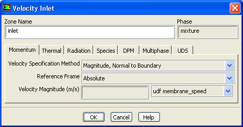
Set the boundary conditions at the inlet (
inlet) for the mixture by selecting
mixture from the
Phase drop-down list in the
Boundary Conditions task page.
 Boundary Conditions

 inlet
inlet
 Edit...
- (a)
Select
udf membrane_speed from the
Velocity Magnitude drop-down list.
- (b)
Click
OK to close the
Velocity Inlet dialog box.
- 2.
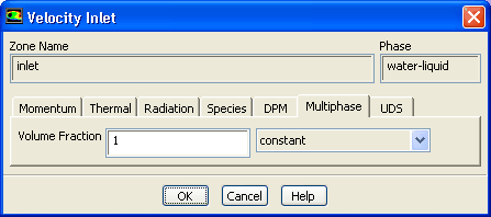
Set the boundary conditions at the inlet (
inlet) for the secondary phase by selecting
water-liquid from the
Phase drop-down list in the
Boundary Conditions task page.
 Boundary Conditions

 inlet
inlet
 Edit...
- (a)
Click the
Multiphase tab and enter
1 for the
Volume Fraction.
- (b)
Click
OK to close the
Velocity Inlet dialog box.
- 3.
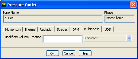
Set the boundary conditions at the outlet (
outlet) for the secondary phase by selecting
water-liquid from the
Phase drop-down list in the
Boundary Conditions task page.
 Boundary Conditions

 outlet
 Edit...
- (a)
Click the
Multiphase tab and retain the default setting of
0 for the
Backflow Volume Fraction.
- (b)
Click
OK to close the
Pressure Outlet dialog box.
- 4.
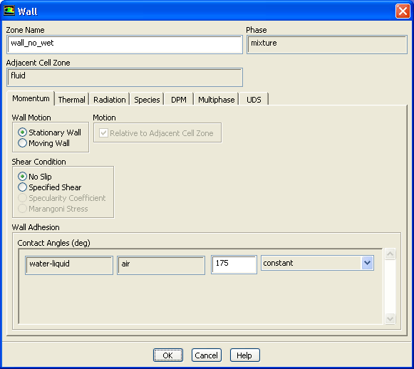
Set the conditions at the top wall of the air chamber (
wall_no_wet) for the mixture by selecting
mixture from the
Phase drop-down list in the
Boundary Conditions task page.
 Boundary Conditions

 wall_no_wet
 Edit...
- (a)
Enter
175 degrees for
Contact Angles.
- (b)
Click
OK to close the
Wall dialog box.
-
Note:
This angle affects the dynamics of droplet formation. You can repeat this simulation to find out how the result changes when the wall is hydrophilic (i.e., using a small contact angle, say 10 degrees).
- 5.
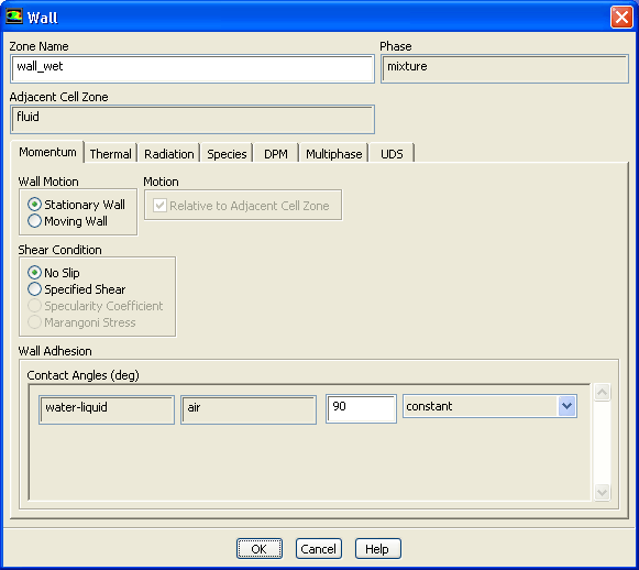
Set the conditions at the side wall of the ink chamber (
wall_wet) for the mixture.
 Boundary Conditions

 wall_wet
 Edit...
- (a)
Retain the default setting of
90 degrees for
Contact Angles.
- (b)
Click
OK to close the
Wall dialog box.
![[ANSYS, Inc. Logo]](fluentlogo.gif)


 Boundary Conditions