- 1.
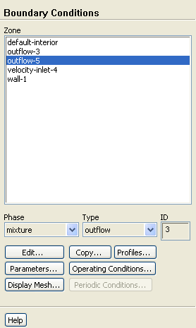
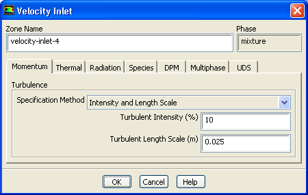
Set the boundary conditions at the velocity inlet (
velocity-inlet-4) for the mixture.
 Boundary Conditions

 velocity-inlet-4
 Edit...
- (a)
Select
Intensity and Length Scale from the
Specification Method drop-down list.
- (b)
Retain the default value of
10
 for
Turbulent Intensity.
for
Turbulent Intensity.
- (c)
Enter
0.025
 for
Turbulent Length Scale.
for
Turbulent Length Scale.
- (d)
Click
OK to close the
Velocity Inlet dialog box.
- 2.
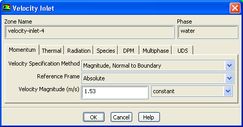
Set the boundary conditions at the velocity inlet (
velocity-inlet-4) for the primary phase (water).
 Boundary Conditions

 velocity-inlet-4
- (a)
Select
water from the
Phase drop-down list.
- (b)
Click
Edit... to open the
Velocity Inlet dialog box.
- i.
Retain the default selection of
Magnitude, Normal to Boundary from the
Velocity Specification Method drop-down list.
- ii.
Retain the default selection of
Absolute from the
Reference Frame drop-down list.
- iii.
Enter
1.53
 for
Velocity Magnitude.
for
Velocity Magnitude.
- iv.
Click
OK to close the
Velocity Inlet dialog box.
- 3.
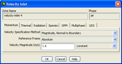
Set the boundary conditions at the velocity inlet (
velocity-inlet-4) for the secondary phase (air).
 Boundary Conditions

 velocity-inlet-4
- (a)
Select
air from the
Phase drop-down list.
- (b)
Click
Edit... to open the
Velocity Inlet dialog box.
- i.
Retain the default selection of
Magnitude, Normal to Boundary from the
Velocity Specification Method drop-down list.
- ii.
Retain the default selection of
Absolute from the
Reference Frame drop-down list.
- iii.
Enter
1.6
 for
Velocity Magnitude.
for
Velocity Magnitude.
-
In multiphase flows, the volume rate of each phase is usually known. Volume rate divided by the inlet area gives the superficial velocity, which is the product of the inlet physical velocity and the volume fraction. When you have two phases, you must enter two physical velocities and the volume fraction of the secondary phase. Here it is assumed that bubbles at the inlet are moving with faster physical speed and their relative velocity with respect to water is
 .
.
- iv.
Click the
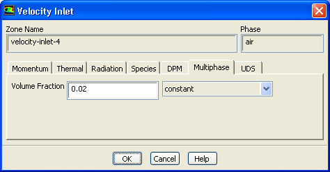
Multiphase tab and enter
0.02 for
Volume Fraction.
- v.
Click
OK to close the
Velocity Inlet dialog box.
- 4.
Set the boundary conditions at
outflow-5 for the mixture.
 Boundary Conditions

 outflow-5
- (a)
Select
mixture from the
Phase drop-down list.
- (b)
Click
Edit... to open the
Outflow dialog box.
- i.
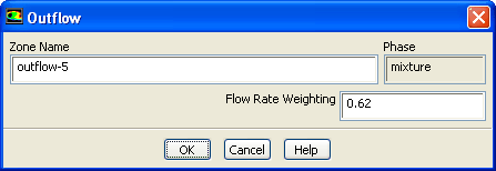
Enter
0.62 for
Flow Rate Weighting.
- ii.
Click
OK to close the
Outflow dialog box.
- 5.
Set the boundary conditions at
outflow-3 for the mixture.
 Boundary Conditions

 outflow-3
 Edit...
- (a)
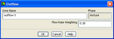
Enter
0.38 for
Flow Rate Weighting.
- (b)
Click
OK to close the
Outflow dialog box.
![[ANSYS, Inc. Logo]](fluentlogo.gif)


 Boundary Conditions