[ANSYS, Inc. Logo] return to home search
next up previous contents

Step 2: General Settings

figure General

1.   Check the mesh.

figure General figure Check

   ANSYS FLUENT will perform various checks on the mesh and report the progress in the console. Ensure hat the reported minimum volume is a positive number.

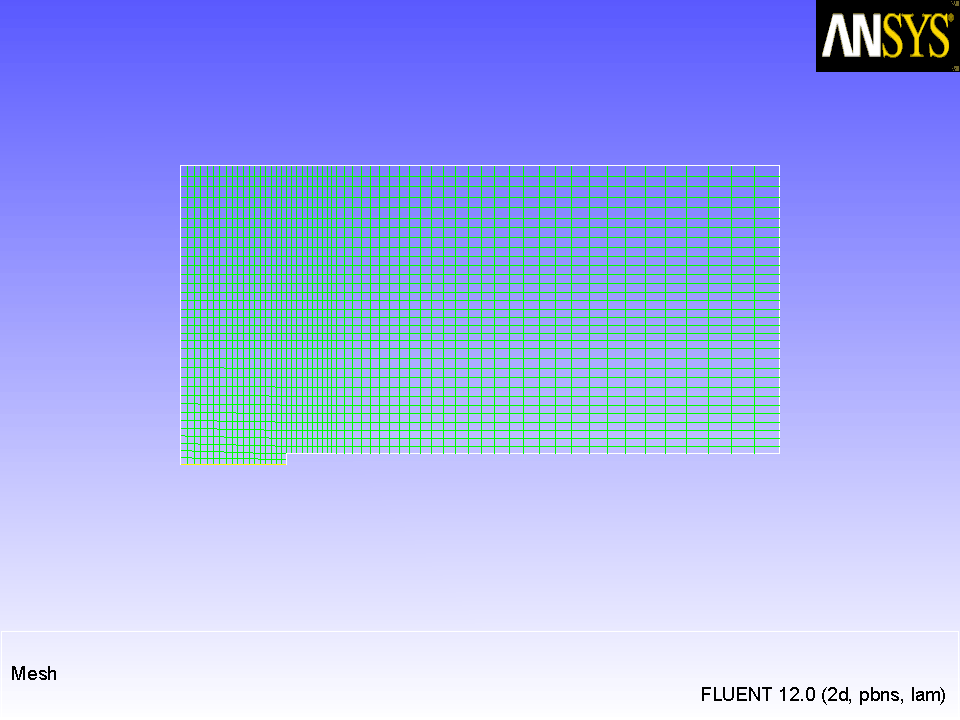
2.   Examine the mesh (Figure  21.2).

Figure 21.2: Mesh Display
figure

Extra:   You can use the right mouse button to check which zone number corresponds to each boundary. If you click the right mouse button on one of the boundaries in the graphics window, its zone number, name, and type will be printed in the console. This feature is especially useful when you have several zones of the same type and you want to distinguish between them quickly.

3.   Modify the mesh colors.

figure General figure Display...

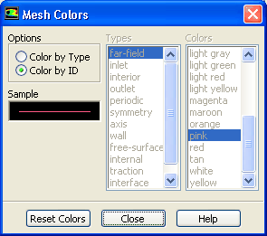
(a)   Click the Colors... button to open the Mesh Colors dialog box.

  You can control the colors used to draw meshes by using the options available in the Mesh Colors dialog box.

figure

i.   Select Color by ID in the Options list.

  This will assign a different color to each zone in the domain, rather than to each type of zone.

ii.   Close the Mesh Colors dialog box.

(b)   Click Display and close the Mesh Display dialog box.

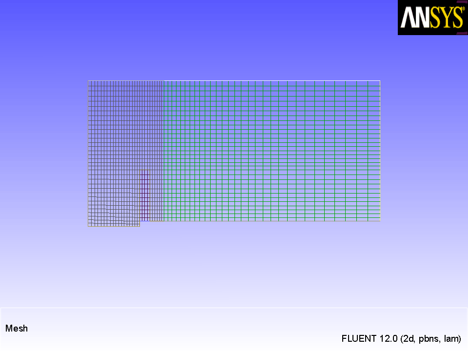
  The graphics display will be updated to show the mesh.

Figure 21.3: Mesh Display Using the Color by ID Option
figure

4.   Modify the view of the mesh display to show the full tank upright.

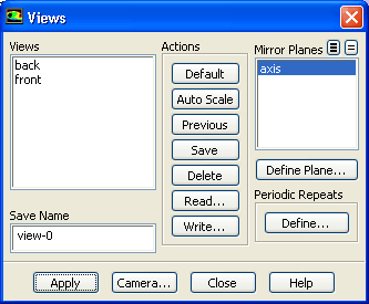
figure Graphics and Animations figure Views...

figure

(a)   Select axis from the Mirror Planes selection list and click Apply.

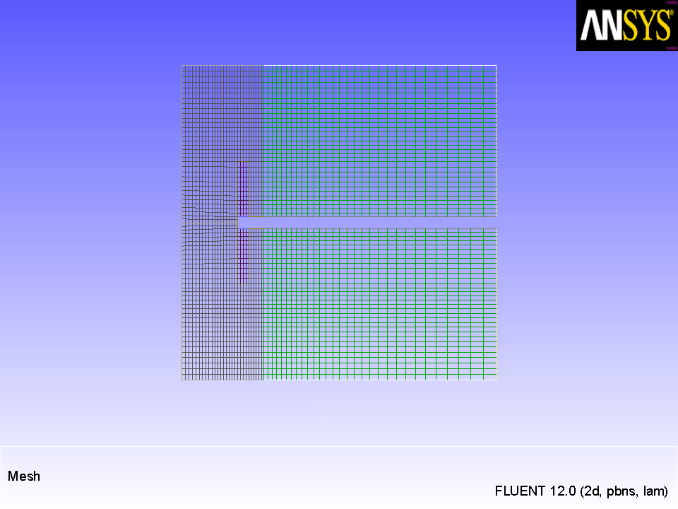
  The mesh display will be updated to show both sides of the tank.

(b)   Click Auto Scale.

  This option is used to scale and center the current display without changing its orientation (Figure  21.4).

Figure 21.4: Mesh Display of the Tank, Mirrored and Scaled
figure

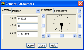
(c)   Click the Camera... button to open the Camera Parameters dialog box.

figure

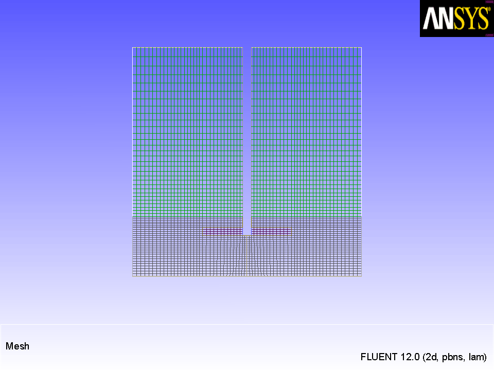
i.   Drag the indicator of the dial with the left mouse button in the counter-clockwise direction until the upright view is displayed (Figure  21.5).

ii.   Click Apply and close the Camera Parameters dialog box.

(d)   Close the Views dialog box.

Note:   While modifying the view, you may accidentally lose the view of the geometry in the display. You can easily revert to the default (front) view by clicking the Default button in the Views dialog box.

Figure 21.5: Mesh Display of the Upright Tank
figure

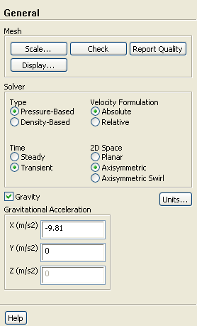
5.   Specify a transient, axisymmetric model.

figure General

figure

(a)   Retain the default Pressure-Based solver.

  The pressure-based solver must be used for multiphase calculations.

(b)   Select Transient in the Time list.

(c)   Select Axisymmetric in the 2D Space list.

6.   Set the gravitational acceleration.

(a)   Enable Gravity.

(b)   Enter -9.81 m/s $^2$ for the Gravitational Acceleration in the X direction.


next up previous contents Previous: Step 1: Mesh
Up: Using the Eulerian Multiphase
Next: Step 3: Models
Release 12.0 © ANSYS, Inc. 2009-02-09