- 1.
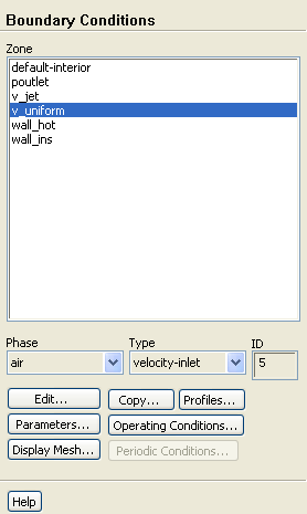
Set the boundary conditions for the lower velocity inlet (
v_uniform) for the primary phase.
 Boundary Conditions

 v_uniform
-
For the Eulerian multiphase model, you will specify conditions at a velocity inlet that are specific to the primary and secondary phases.
- (a)
Select
air from the
Phase drop-down list.
- (b)
Click the
Edit... button to open the
Velocity Inlet dialog box.
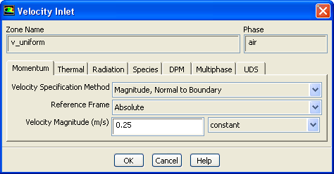
- i.
Retain the default selection of
Magnitude, Normal to Boundary from the
Velocity Specification Method drop-down list.
- ii.
Enter
0.25 m/s for the
Velocity Magnitude.
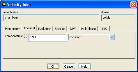
- iii.
Click the
Thermal tab and enter
293 K for
Temperature.
- iv.
Click
OK to close the
Velocity Inlet dialog box.
- 2.
Set the boundary conditions for the lower velocity inlet (
v_uniform) for the secondary phase.
 Boundary Conditions

 v_uniform
- (a)
Select
solids from the
Phase drop-down list.
- (b)
Click the
Edit... button to open the
Velocity Inlet dialog box.
- i.
Retain the default
Velocity Specification Method and
Reference Frame.
- ii.
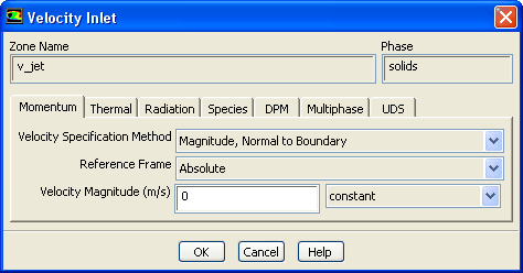
Retain the default value of
0 m/s for the
Velocity Magnitude.
- iii.
Click the
Thermal tab and enter
293 K for
Temperature.
- iv.
Click the
Multiphase tab and retain the default value of
0 for
Volume Fraction.
- v.
Click
OK to close the
Velocity Inlet dialog box.
- 3.
Set the boundary conditions for the orifice velocity inlet (
v_jet) for the primary phase.
 Boundary Conditions

 v_jet
v_jet
- (a)
Select
air from the
Phase drop-down list.
- (b)
Click the
Edit... button to open the
Velocity Inlet dialog box.
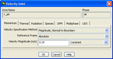
- i.
Retain the default
Velocity Specification Method and
Reference Frame.
- ii.
Enter
0.25 m/s for the
Velocity Magnitude.
-
In order for a comparison with analytical results [1] to be meaningful, in this simulation you will use a uniform value for the air velocity equal to the minimum fluidization velocity at both inlets on the bottom of the bed.
- iii.
Click the
Thermal tab and enter
293 K for
Temperature.
- iv.
Click
OK to close the
Velocity Inlet dialog box.
- 4.
Set the boundary conditions for the orifice velocity inlet (
v_jet) for the secondary phase.
 Boundary Conditions

 v_jet
v_jet
- (a)
Select
solids from the
Phase drop-down list.
- (b)
Click the
Edit... button to open the
Velocity Inlet dialog box.
- i.
Retain the default
Velocity Specification Method and
Reference Frame.
- ii.
Retain the default value of
0 m/s for the
Velocity Magnitude.
- iii.
Click the
Thermal tab and enter
293 K for
Temperature.
- iv.
Click the
Multiphase tab and retain the default value of
0 for the
Volume Fraction.
- v.
Click
OK to close the
Velocity Inlet dialog box.
- 5.
Set the boundary conditions for the pressure outlet (
poutlet) for the mixture phase.
 Boundary Conditions

 poutlet
-
For the Eulerian granular model, you will specify conditions at a pressure outlet for the mixture and for both phases.
-
The thermal conditions at the pressure outlet will be used only if flow enters the domain through this boundary. You can set them equal to the inlet values, as no flow reversal is expected at the pressure outlet. In general, however, it is important to set reasonable values for these downstream scalar values, in case flow reversal occurs at some point during the calculation.
- (a)
Select
mixture from the
Phase drop-down list.
- (b)
Click the
Edit... button to open the
Pressure Outlet dialog box.
- i.
Retain the default value of
0 Pascal for
Gauge Pressure.
- ii.
Click
OK to close the
Pressure Outlet dialog box.
- 6.
Set the boundary conditions for the pressure outlet (
poutlet) for the primary phase.
 Boundary Conditions

 poutlet
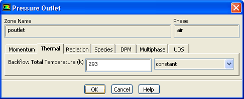
- (a)
Select
air from the
Phase drop-down list.
- (b)
Click the
Edit... button to open the
Pressure Outlet dialog box.
- i.
Click the
Thermal tab and enter
293 K for
Backflow Total Temperature.
- ii.
Click
OK to close the
Pressure Outlet dialog box.
- 7.
Set the boundary conditions for the pressure outlet (
poutlet) for the secondary phase.
 Boundary Conditions

 poutlet
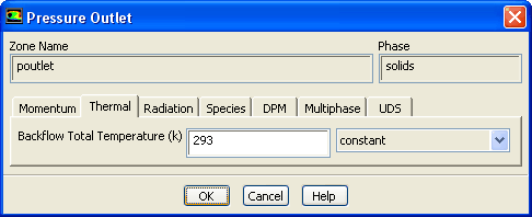
- (a)
Select
solids from the
Phase drop-down list.
- (b)
Click the
Edit... button to open the
Pressure Outlet dialog box.
- i.
Click the
Thermal tab and enter
293 K for the
Backflow Total Temperature.
- ii.
Click the
Multiphase tab and retain default settings.
- iii.
Click
OK to close the
Pressure Outlet dialog box.
- 8.
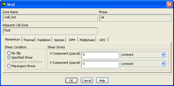
Set the boundary conditions for the heated wall (
wall_hot) for the mixture.
 Boundary Conditions

 wall_hot
-
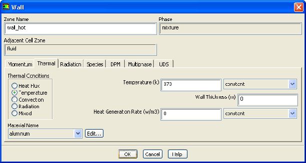
For the heated wall, you will set thermal conditions for the mixture, and momentum conditions (zero shear) for both phases.
- (a)
Select
mixture from the
Phase drop-down list.
- (b)
Click the
Edit... button to open the
Wall dialog box.
- i.
Click the
Thermal tab.
- a.
Select
Temperature from the
Thermal Conditions list.
- b.
Enter
373 K for
Temperature.
- ii.
Click
OK to close the
Wall dialog box.
- 9.
Set the boundary conditions for the heated wall (
wall_hot) for the primary phase.
 Boundary Conditions

 wall_hot
- (a)
Select
air from the
Phase drop-down list.
- (b)
Click the
Edit... button to open the
Wall dialog box.
- i.
Select
Specified Shear from the
Shear Condition list.
-
The
Wall dialog box will expand.
- ii.
Retain the default value of
0 for
X-Component and
Y-Component.
- iii.
Click
OK to close the
Wall dialog box.
- 10.
Set the boundary conditions for the heated wall (
wall_hot) for the secondary phase same as that of the primary phase.
 Boundary Conditions

 wall_hot
-
For the secondary phase, you will set the same conditions of zero shear as for the primary phase.
- 11.
Set the boundary conditions for the adiabatic wall (
wall_ins) for the primary phase.
 Boundary Conditions

 wall_ins
-
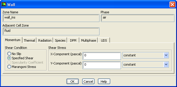
For the adiabatic wall, you will retain the default thermal conditions for the mixture (zero heat flux), and set momentum conditions (zero shear) for both phases.
- (a)
Select
air from the
Phase drop-down list.
- (b)
Click the
Edit... button to open the
Wall dialog box.
- i.
Select
Specified Shear from the
Shear Condition list.
-
The
Wall dialog box will expand.
- ii.
Retain the default value of
0 for
X-Component and
Y-Component.
- iii.
Click
OK to close the
Wall dialog box.
- 12.
Set the boundary conditions for the adiabatic wall (
wall_ins) for the secondary phase same as that of the primary phase.
 Boundary Conditions

 wall_ins
-
For the secondary phase, you will set the same conditions of zero shear as for the primary phase.
![[ANSYS, Inc. Logo]](fluentlogo.gif)


 Boundary Conditions