(a)
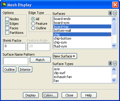
Retain the default selection of
Edges in the
Options group box.
(b)
Deselect all surfaces and select
board-top and
chip from the
Surfaces selection list.
To deselect all surfaces click on the far-right unshaded button at the top of the
Surfaces selection list, and then select the desired surfaces from the
Surfaces selection list.
(c)
Click the
Colors... button to open the
Mesh Colors dialog box.
i.
Select
Color by ID in the
Options group box.
ii.
Click
Reset Colors and close the
Mesh Colors dialog box.
(d)
Click
Display.
2.
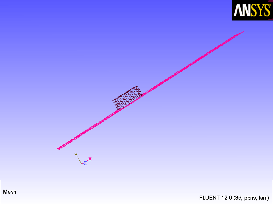
Rotate and zoom the view.
Use the left mouse button to rotate the view. Use the middle mouse button to zoom the view until you obtain an enlarged display of the circuit board in the region of the chip, as shown in Figure
24.2.
Figure 24.2: Mesh Display of the Chip and Board Surfaces
Extra:
You can click the right mouse button on one of the boundaries displayed in the graphics window and its zone number, name, and type will be printed in the console. This feature is especially useful when you have several zones of the same type and you want to distinguish between them.
3.
Display the mesh faces.
GeneralDisplay...
(a)
Disable
Edges and enable
Faces in the
Options group box.
(b)
Click
Display and close the
Mesh Display dialog box.
The surfaces run together with no shading to separate the chip from the board.
![[ANSYS, Inc. Logo]](fluentlogo.gif)


 General
 General
 Display...
 General
 Display...