[ANSYS, Inc. Logo] return to home search
next up previous contents

Step 4: Creating Isosurfaces

  To display results in a 3D model, you will need surfaces on which the data can be displayed. ANSYS FLUENT creates surfaces for all boundary zones automatically. Several surfaces have been renamed after reading the case file. Examples are board-sym and board-ends, which correspond to the side and end faces of the circuit board.

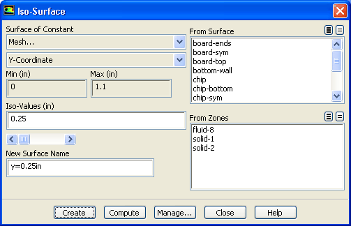
You can define additional surfaces for viewing the results, for example, a plane in Cartesian space. In this exercise, you will create a horizontal plane cutting through the middle of the module with a $y$ value of 0.25 inches. You can use this surface to display the temperature and velocity fields.

1.   Create a surface of constant $y$ coordinate.

Surface $\rightarrow$ Iso-Surface...

figure

(a)   Select Mesh... and Y-Coordinate from the Surface of Constant drop-down lists.

(b)   Click Compute.

  The Min and Max fields will display the $y$ extents of the domain.

(c)   Enter 0.25 for Iso-Values.

(d)   Enter y=0.25in for New Surface Name.

(e)   Click Create and close the Iso-Surface dialog box.

2.   Create a clipped surface for the X-coordinate of the fluid ( fluid-sym).

Surface $\rightarrow$ Iso-Clip...

figure

(a)   Select Mesh... and X-Coordinate from the Clip to Values of drop-down lists.

(b)   Select fluid-sym from the Clip Surface selection list.

(c)   Click Compute.

  The values will be displayed in the Min and Max fields.

(d)   Enter 1.9 and 3.9 for Min and Max respectively.

Note:   This will isolate the area around the chip.

(e)   Enter fluid-sym-x-clip for New Surface Name.

(f)   Click Clip.

3.   Create a clipped surface for the Y-coordinate of the fluid ( fluid-sym).

Surface $\rightarrow$ Iso-Clip...

figure

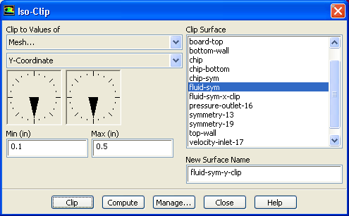
(a)   Select Mesh... and Y-Coordinate from the Clip to Values of drop-down lists.

(b)   Retain the selection of fluid-sym from the Clip Surface selection list.

(c)   Click Compute.

  The values will be displayed in the Min and Max fields.

(d)   Enter 0.1 and 0.5 for Min and Max respectively.

Note:   This will isolate the area around the chip.

(e)   Enter fluid-sym-y-clip for New Surface Name.

(f)   Click Clip and close the Iso-Clip dialog box.


next up previous contents Previous: Step 3: Adding Lights
Up: Postprocessing
Next: Step 5: Contours
Release 12.0 © ANSYS, Inc. 2009-02-09