![[ANSYS, Inc. Logo]](fluentlogo.gif)


|
|
|
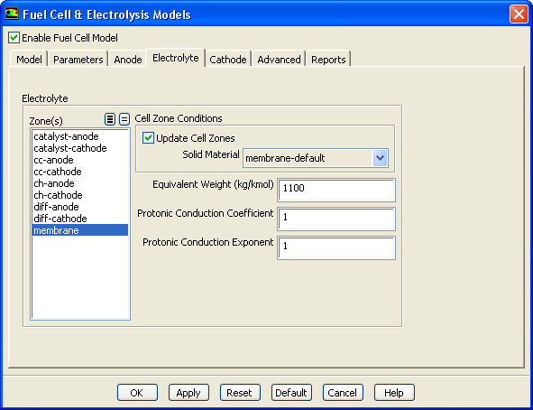
You can use the Electrolyte tab of the Fuel Cell and Electrolysis Models dialog to specify zones and properties of the electrolyte/membrane portion of the fuel cell.
 in Equation
1.6-6).
in Equation
1.6-6).
 in Equation
1.6-4). This is used to calculate the membrane phase electric conductivity.
in Equation
1.6-4). This is used to calculate the membrane phase electric conductivity.
 in Equation
1.6-4).
in Equation
1.6-4).
Note that the Fuel Cell and Electrolysis Model allows you to model the electrolyte/membrane as either a fluid zone or as a solid zone. For PEMFC, the Fuel Cell and Electrolysis Model still allows for water and the ionic current to pass through the electrolyte/membrane.
Specifying Cell Zone Conditions for the Membrane
When you assign a solid material to the membrane, you are setting a cell zone condition. With the Update Cell Zones option turned on (the default setting), this cell zone condition is applied to all selected zones in the Zone(s) list. If you want to set the cell zone conditions for each zone individually (using the Cell Zone Conditions task page), you should turn off the Update Cell Zones option.
Previous:
2.6.3 Specifying Anode Properties