You can use the
Anode tab of the
Fuel Cell and Electrolysis Models dialog to specify zones and properties of the current collector, the flow channel, the diffusion layer, and the catalyst layer for the anode portion of the fuel cell.
Specifying Current Collector Properties for the Anode
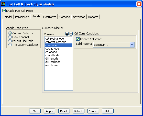
Figure 2.6.4: The
Anode Tab of the
Fuel Cell and Electrolysis Models Dialog With
Current Collector Selected
1.
Select the
Anode tab of the
Fuel Cell and Electrolysis Models dialog.
2.
Select
Current Collector under
Anode Zone Type.
3.
Select a corresponding zone from the
Zone(s) list. If you are modeling a fuel cell stack, then you must pick
all zones of a particular type as a group.
4.
Select a
Solid Material from the corresponding drop-down list. Solid materials can be customized using the
Create/Edit Materials dialog. Note that for the
Electrical Conductivity, you can only choose a constant value in the
Create/Edit Materials dialog. The solid electrical conductivity value is the diffusivity of the solid phase potential in the solid zones.
Specifying Flow Channel Properties for the Anode
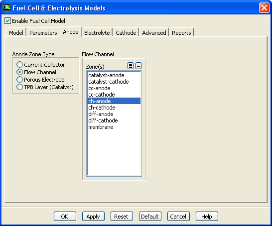
Figure 2.6.5: The
Anode Tab of the
Fuel Cell and Electrolysis Models Dialog With
Flow Channel Selected
1.
Select the
Anode tab of the
Fuel Cell and Electrolysis Models dialog.
2.
Select
Flow Channel under
Anode Zone Type.
3.
Select a corresponding zone from the
Zone(s) list.
Specifying Porous Electrode Properties for the Anode
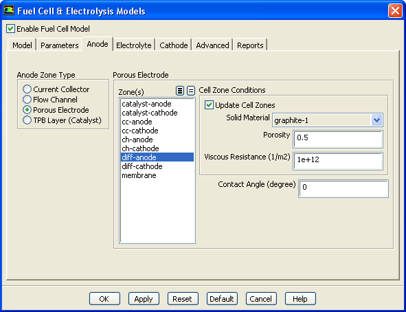
Figure 2.6.6: The
Anode Tab of the
Fuel Cell and Electrolysis Models Dialog With
Porous Electrode Selected
1.
Select the
Anode tab of the
Fuel Cell and Electrolysis Models dialog.
2.
Select
Porous Electrode under
Anode Zone Type.
3.
Select a corresponding zone from the
Zone(s) list. If you are modeling a fuel cell stack, then you must pick
all zones of a particular type as a group.
4.
Select a
Solid Material from the corresponding drop-down list. Solid materials can be customized using the
Create/Edit Materials dialog. Note that for the
Electrical Conductivity, you can only choose a constant value in the
Create/Edit Materials dialog. The solid electrical conductivity value is the diffusivity of the solid phase potential in the solid zones.
5.
Specify a value for the
Porosity.
6.
Specify a value for the
Viscous Resistance.
7.
Specify a value for the
Contact Angle for multiphase fuel cell calculations (
inEquation
1.5-4).
Specifying Catalyst Layer Properties for the Anode
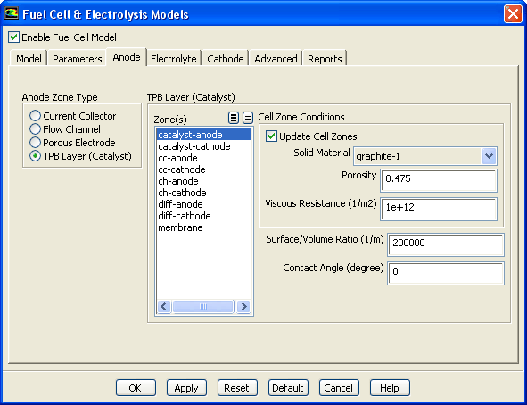
Figure 2.6.7: The
Anode Tab of the
Fuel Cell and Electrolysis Models Dialog With
TPB Layer - Catalyst Selected
1.
Select the
Anode tab of the
Fuel Cell and Electrolysis Models dialog.
2.
Select
TPB Layer (Catalyst) under
Anode Zone Type.
3.
Select a corresponding zone from the
Zone(s) list. If you are modeling a fuel cell stack, then you must pick
all zones of a particular type as a group.
4.
Select a
Solid Material from the corresponding drop-down list. Solid materials can be customized using the
Create/Edit Materials dialog. Note that for the
Electrical Conductivity, you can only choose a constant value in the
Create/Edit Materials dialog. The solid electrical conductivity value is the diffusivity of the solid phase potential in the solid zones.
5.
Specify a value for the
Porosity.
6.
Specify a value for the
Viscous Resistance.
7.
Specify a value for the
Surface/Volume Ratio (the specific active surface area in Equation
1.2-3).
8.
Specify a value for the
Contact Angle for multiphase fuel cell calculations (
inEquation
1.5-4).
Specifying Cell Zone Conditions for the Anode
For each case of the anode's current collector, diffusion layer, and catalyst layer, you assign a solid material and/or set the porosity and the viscous resistance. These settings represent setting a cell zone condition. With the
Update Cell Zones option turned on (the default setting), this cell zone condition is applied to all selected zones in the
Zone(s) list. If you want to set the cell zone conditions for each zone individually (using the
Cell Zone Conditions task page), you should turn off the
Update Cell Zones option.
![[ANSYS, Inc. Logo]](fluentlogo.gif)


 inEquation
1.5-4).
inEquation
1.5-4).
 inEquation
1.5-4).
inEquation
1.5-4).