![[ANSYS, Inc. Logo]](fluentlogo.gif)


|
|
|
Boundary conditions related to MHD calculations are set under the Boundary Condition tab in the MHD Model dialog box. Boundary conditions can be set to cell zones and wall boundaries.
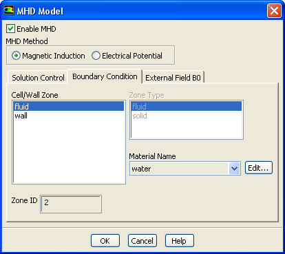
For cell zones, only the associated material can be changed and its properties modified. Figure 4.3.7 shows the dialog box for cell zone boundary condition setup. The cell zone material can be selected from the Material Name drop-down list.
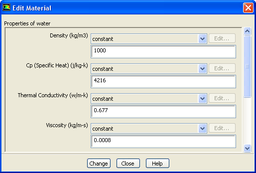
Note that the materials available in the list are set in the general ANSYS FLUENT case setup. Please refer to the ANSYS FLUENT User Guide for details on adding materials to an ANSYS FLUENT case. The properties of the selected material can be modified in the Boundary Condition tab by clicking on the Edit... button to the right of the material name. This will open the Edit Material dialog box, as shown in Figure 4.3.8. The material properties that may be modified include the electrical conductivity and magnetic permeability. The material electrical conductivity can be set as constant, a function of temperature in forms of piecewise-linear, piecewise-polynomial or polynomial, or as a user-defined function. The material magnetic permeability can only be set as a constant.
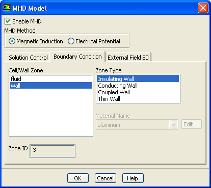
For wall boundaries, the boundary condition can be set as an Insulating Wall, Conducting Wall, Coupled Wall or Thin Wall. The dialog box for wall boundary condition setup is shown in Figure 4.3.9.
For conducting walls and thin wall boundaries, the wall material can be selected from the Material Name drop-down list, and its properties modified through the Edit Material dialog box. A wall thickness needs to be specified for thin wall type boundaries.
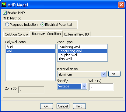
If the Electric Potential method is selected, the conducting wall boundary is specified by either of Voltage or Current Density at the boundary, as shown in Figure 4.3.10.
Previous:
4.3.3 Applying an External