- 1.
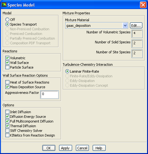
Enable
Volumetric for the reacting flow solution.
 Models

 Species
 Edit...
- (a)
Enable
Volumetric
and
Wall Surface
in the
Reactions group box.
- (b)
Enable
Mass Deposition Source in the
Wall Surface Reaction Options group box.
- (c)
Click
OK to close the
Species Model dialog box.
- 2.
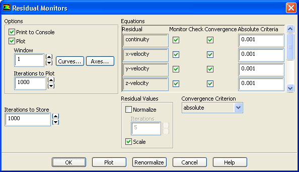
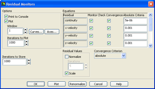
Retain the default convergence criteria for calculation.
 Monitors

 Residuals
 Edit...
- 3.
Request 250 more iterations.
 Run Calculation
-
The solution will converge in approximately 75 iterations.
- 4.
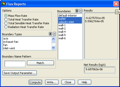
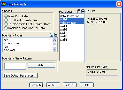
Compute the mass fluxes.
 Reports

 Fluxes
 Set Up...
- (a)
Retain the default selection of
Mass Flow Rate in the
Options group box.
- (b)
Select
outlet and
velocity-inlet from the
Boundaries selection list.
- (c)
Click
Compute and close the
Flux Reports dialog box.
- 5.
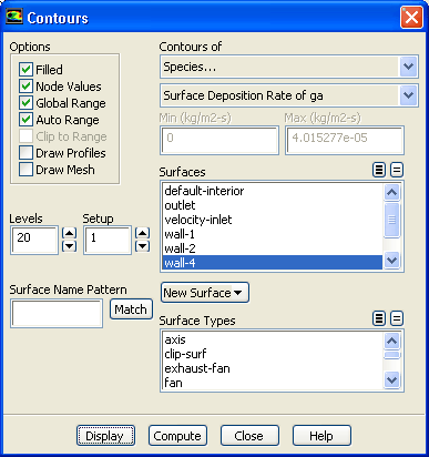
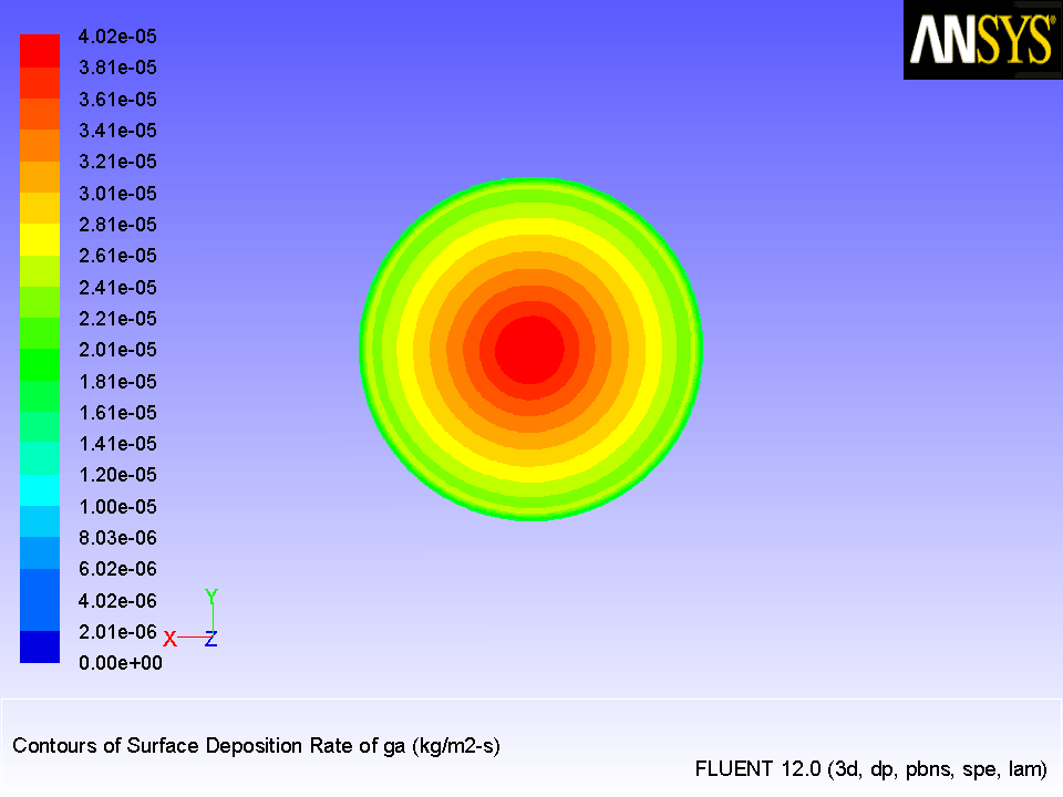
Display contours of surface deposition rate of
ga (Figure
16.3).
 Graphics and Animations

 Contours
 Set Up...
- (a)
Enable
Filled in the
Options group box.
- (b)
Select
Species... and
Surface Deposition Rate of ga from the
Contours of drop-down lists.
- (c)
Select
wall-4 from the
Surfaces selection list.
- (d)
Click
Display and close the
Contours dialog box.
-
Rotate the display with the mouse to obtain the view as shown in (Figure
16.3).
Figure 16.3: Contours of
Surface Deposition Rate of
ga
 |
- 6.
Reduce the convergence criteria.
 Monitors

 Residuals
 Edit...
- (a)
Enter
5e-06 for
Absolute Criteria for
continuity.
- (b)
Click
OK to close the
Residual Monitors dialog box.
- 7.
Request 300 more iterations.
 Run Calculation
-
The solution will converge in approximately 190 iterations.
- 8.
Check the mass fluxes.
 Reports

 Fluxes
 Set Up...
- (a)
Retain the default selection of
Mass Flow Rate in the
Options group box.
- (b)
Retain the selection of
outlet and
velocity-inlet in the
Boundaries selection list.
- (c)
Click
Compute and close the
Flux Reports dialog box.
- 9.
Save the case and data files (
surface-react1.cas.gz and
surface-react1.dat.gz).
File
 Write
Write
 Case & Data...
- 10.
Display contours of surface deposition rate of
ga (Figure
16.4).
 Graphics and Animations

 Contours
 Set Up...
Figure 16.4: Contours of
Surface Deposition Rate of
ga
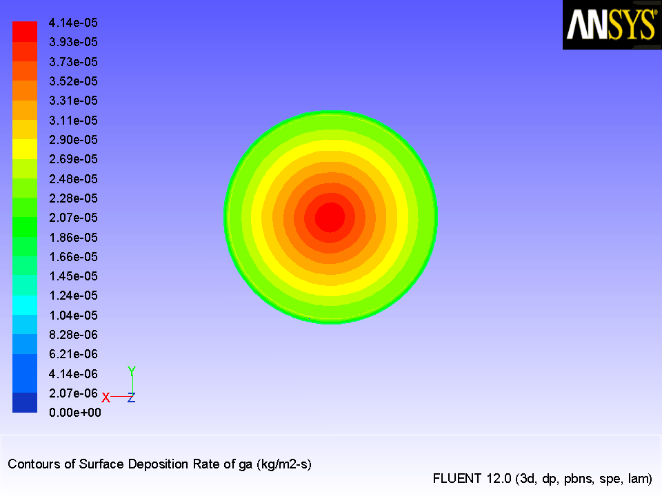 |
Figure 16.5: Scaled Residuals
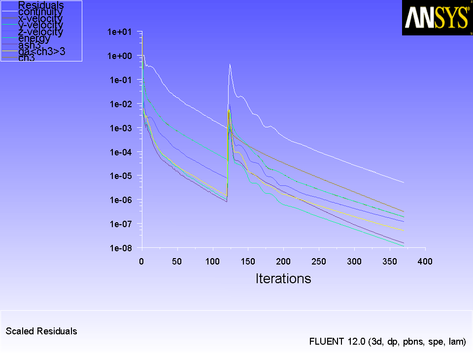 |
![[ANSYS, Inc. Logo]](fluentlogo.gif)