-
A UDF is used to specify the fixed velocities that simulate the impeller. The values of the time-averaged impeller velocity components and turbulence quantities are based on experimental measurement. The variation of these values may be expressed as a function of radius, and imposed as polynomials according to:
-
The order of polynomial to be used depends on the behavior of the function being fitted. For this tutorial, the polynomial coefficients shown in Table
21.1 are provided in the UDF
fix.c.
For more informtion about setting up a UDF using the
DEFINE_PROFILE macro, refer to the separate
UDF Manual. Though this macro is usually used to specify a profile condition on a boundary face zone, it is used in
fix.c to specify the condition in a fluid cell zone. Hence, the arguments of the macro have been changed accordingly.
- 1.
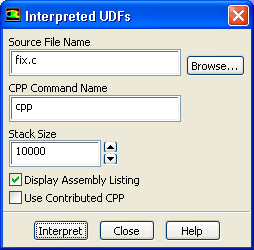
Interpret the UDF source file
fix.c.
Define
 User-Defined
 Functions
 Interpreted...
- (a)
Enter
fix.c for
Source File Name.
-
If the UDF source file is not in your working folder, you must enter the entire folder path for
Source File Name instead of just entering the file name. Alternatively, click
Browse... and select
fix.c in the
eulerian_multiphase_granular folder that was created after you unzipped the original file.
- (b)
Enable
Display Assembly Listing.
-
The
Display Assembly Listing option displays the assembly language code in the console as the function compiles.
- (c)
Click
Interpret to interpret the UDF.
- (d)
Close the
Interpreted UDFs dialog box.
-
Note:
The name and contents of the UDF are stored in the case file when you save the case file.


 Previous:
Step 5: Phases
Previous:
Step 5: Phases
Up:
Using the Eulerian Multiphase
Next:
Step 7: Cell Zone
Release 12.0 © ANSYS, Inc. 2009-02-09 ![[ANSYS, Inc. Logo]](fluentlogo.gif)





 velocity
 velocity