![[ANSYS, Inc. Logo]](fluentlogo.gif)


|
|
|
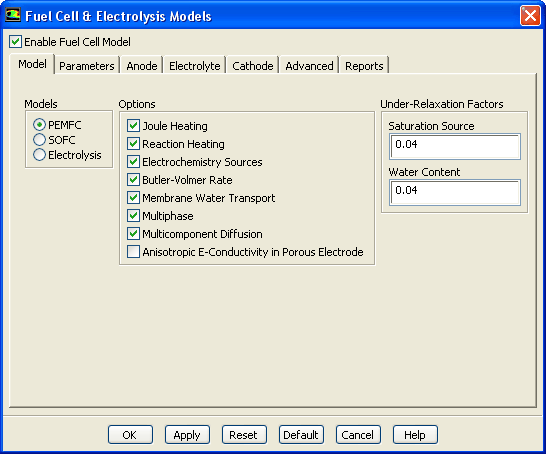
The Model tab of the Fuel Cell and Electrolysis Models dialog allows you to turn on or off various options when solving a fuel cell problem. To model polymer electrolyte membrane fuel cells, enable the PEMFC option in the Model tab. Likewise, to model solid oxide fuel cells, enable the SOFC option in the Model tab. Finally, to model electrolysis, enable the Electrolysis option in the Model tab.
Several fuel cell model options are available in the Model tab of the Fuel Cell and Electrolysis Models dialog including:
 term in the energy source term from Equation
1.4-1 in the calculations.
term in the energy source term from Equation
1.4-1 in the calculations.
 term, and the product of transfer current and the over-potentials in the energy source term from Equation
1.4-1 in the calculations.
term, and the product of transfer current and the over-potentials in the energy source term from Equation
1.4-1 in the calculations.
Due to the fibrous structure of the porous material that is used for the electrodes (or gas diffusion layer), the electrical conductivity is typically non-isotropical, with the cross-plane components being orders of magnitude smaller than the in-plane components. This can be modeled using the Anisotropic E-Conductivity in Porous Electrode setting. When this option is enabled, the Electrical Conductivity for the solid material used in the electrolyte is no longer used. Instead, you need to specify, for this solid material, the electrical conductivity by choosing one of the three non-isotropical options for the UDS diffusivity ( UDS-0). The three options are: anisotropic; orthotropic; and cyl-orthotropic. For more information about these UDS Diffusivity options, refer to the ANSYS FLUENT User's Guide.
For example, to use this feature, perform the following steps:
|
|
Note that, in this case, the
Electrical Conductivity for
this solid material is ignored.
|
The saturation source term
 in Equation
1.5-2 usually requires under-relaxation. You can change the default value for the under-relaxation factor by changing the value for
Saturation Source.
in Equation
1.5-2 usually requires under-relaxation. You can change the default value for the under-relaxation factor by changing the value for
Saturation Source.
The water content,
 , in Equation
1.6-8 also may need under-relaxation. You can change the default value for the under-relaxation factor by changing the value for
Water Content.
, in Equation
1.6-8 also may need under-relaxation. You can change the default value for the under-relaxation factor by changing the value for
Water Content.
Nearly all options are turned on by default. You may wish to override the default values, depending on the problem you wish to model. For instance, if you are not concerned with the heat generated due to chemical reaction, then you may want to turn off the Reaction Heating option.
Previous:
2.6 Modeling Fuel Cells